In my travels I do a fair amount of straight up electrical work. I see my share of shorts, drains, and inoperative components at shops. I have always liked electrical work and it something for the most part shops tend to shy away from. Usually, tracing a short or getting into a battery drain is not as profitable as a brake job and can take up a lot of the techs/shops time. In todays vehicles there are literally hundereds of connections strewn throughout the vehicle. I wanted to share with you a couple I have encountered recently with a common theme-bad connections.

First up is a 2007 Cadillac Escalade EXT with climate control seat issues. This vehicle has both heated and cooled front seating with a mini blower motor for each seat. This is all controlled by the CCSM (Climate Control Seating Module) under the passenger front seat. I first became involved with this when the shop called asking me if I could program a new CCSM they were going to install in this vehicle for the problem of no operation of climate controlled seating. The dealer told the shop it needed to be programmed. Most GM modules do need to be programmed. A quick check of service information revealed this did not need programming it was "plug and play". I advised the shop of this and they installed the new CCSM and still had no climate control seat operation. That is where I came in. I first verified proper inputs to the CCSM with my Tech2 and also backprobed powers and grounds at the CCSM. All were good. Why wasn't it working?
Let's disconnect the connector and check for pin deformation, etc.
Well here we go. The main power feed terminal for the CCSM is smoked. I checked resistances of the seat heaters and blower motors from the disconnected connector. All were in specifications. I then amp drawed the circuits to check them dynamically and again all were good. A lot of current under the best of circumstances goes through this terminal. Better to be safe than sorry. A call to the dealer revealed they had this pigtail in stock-no suprise there, huh? A new pigtail was installed and we can now keep our butt warm in the winter and cool in the summer. How did we ever do without this?
Next up is a 2003 Toyota Sequoia that the battery would go dead overnight intermittently. The customer swears the headlamps turn on by themselves causing this. The shop has already installed a brand new battery and has never seen this phantom headlamp issue. I get called in and for the first couple of minutes of me manipulating switches and harnesses nothing happens. I turn my head and then look back and the headlamps are on and the switch is off and I have the keys in my hand. A second look and actually the DRL (Daytime Running Lamps) are on. DRL operation is controlled by the Body ECU. I hook up my Toyota Techstream scantool and I see no reason the Body ECU should be putting on the DRL lamps. I try to toggle the DRL relay on and off through the bi-directional functions of the scanner and they just stay on. Could the Body ECU be bad. Well, it is easy enough to disconnect. I do so and the lamps stay on. Do I have a stuck DRL relay? I don't think so since the vehicle should not have had the DRL lamps on to begin with key off. Hmm. Whenever I see phantom issues like this I think of two things-resistive shorts caused by moisture intrusion or bad grounds backfeeding. A quick voltage drop of ground circuits reveals excellent grounds. I am going for the resistive short. I start wiggling connections at the inerior fusebox which also serves as a junction box for many circuits including the DRL's and the lamps flicker. I trace the circuit to a particular connector at the fusebox. I cannot get this connector out of the fusebox. I have pliers on it and I do not want to break it off. I pull an adjacent connector at the fusebox and there are signs of moisture. There is green corrosion all over. I tell the shop owner he needs a fusebox. We finally get the connections out-here is the fusebox.

Taken on some water here for sure. A tech in the shop told me that this vehicle sees a decent amount of beach time in the summer months. Maybe, he got caught in the waves one time. Or, perhaps an old windshield leak. Here is another shot.
The moisture migrated into the fusebox and caused circuits internal to have continuity when they should not have. At first the shop owner asked me if we could save this fusebox. Not a chance!
This next one is from a body shop I service. It is a 2001 Ford Windstar with no rear lighting. Front lighting is operative. This vehicle uses a REM (Rear Electronics Module) to control the rear lighting. It is nestled over in the right rear of the vehicle behind a trim panel-see below.

I hook up my scantool to make sure it is communicating and getting proper inputs and to test the outputs. It is communicating and getting proper inputs. When I try to do output tests for the relays that control rear lighting via the REM-I hear nothing. A look at the diagram tells me that the relay command wire goes straight from the REM to the junction box under the left side of the dash. There are no connectors in between! So no divide and conquer mentality can be used here. To make matters worse the interior of this vehicle is fully intact. Usually, when I get a call from a body shop the interior is torn apart which makes it easier for me. This harness goes across the interior of the vehicle. So, I am thinking is a harness chafed on a seat anchor or rotted right in the middle of the truck. The nightmare scenario of taking this Windstar apart is gnawing at me. I know that the connections at the REM look good. I jump out the relay at the junction box and the rear lighting comes to life. So I know there is an issue at the control for the relay. Let's head for the junction box connector on the back that has the control circuit wire.

Well lookey here. I knew something was up when the connector was a bit of a pain to get out. Yes, water intrusion and Yes there should be four terminals on the top row and four terminals on the bottom. See what is missing?
There is the missing pin welded into the female terminal of the connector. This Windstar I believe has a windshield leak that started this ball rolling.
Finally, we have another fine GM vehicle. A 2006 Cadillac Escalade with complaints of no rear wiper and no rear defroster operation. I hooked up my Tech2 expecting to see a LGM (Liftgate Module) and start my diagnostics from there. No LGM showed up. A check of the wiring revealed no LGM on this vehicle and basically was old school from switch to wiper motor. With the rear liftgate open and the shop owner manipulating the rear wiper switch the interior lamps would come on or go out. That was my first clue where to go. Remember, phantom issues either resistive power shorts or bad grounds. I checked the ground at the wiper motor and depending on where the rear wiper switch was it was anywhere from 2.0v to 10.0v back to battery negative using voltage drop. Ok, we know we have a bad ground. The ground itself is behind the right rear interior panel. I really hate pulling panels when I do not have to. Lets check it at the liftgate connector that is easier.

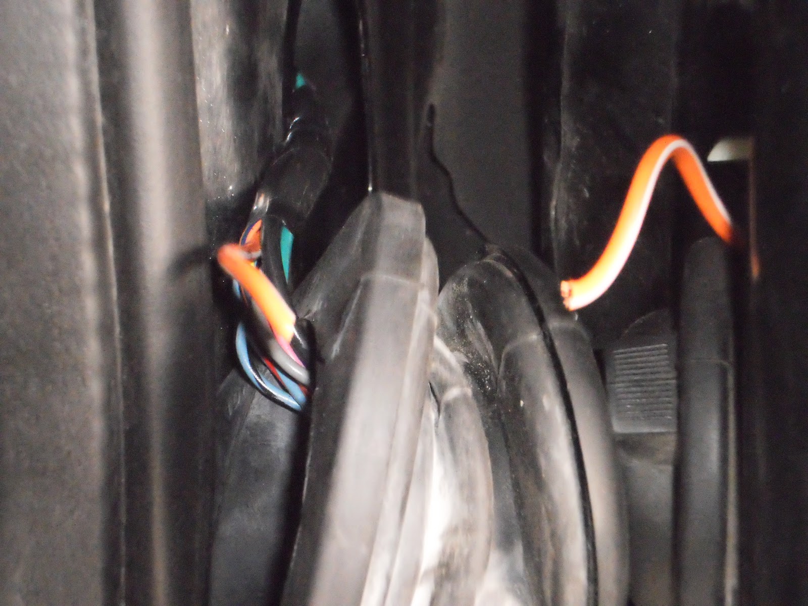
I move this connector and my voltage drop fluctuates. Lets check the connector ends. I smell bad connection.
Here is one side of the connector.
The other side of the connector. Sorry, for the blurry pictures-you get the idea. Again, a substantial amount of current goes through here. Any loose connection, added resistance, etc will cause this. Terminal repair to the connector and this vehicle was back in action.