Thursday, April 9, 2015

Square Peg Round Hole


I get a call from a shop that uses me regularly. He has this 2002 Jeep Liberty with 127,629 miles with a 3.7 Liter motor. He just swapped a salvaged motor in it and now it doesn't start. This shop does a lot of motor swapping. Every time I go to this shop there seems to be some type of motor being swung in and out. I arrive at the shop and do a quick visual on the installation. I crank the vehicle over and it doesn't start at all. Not even an attempt. Where to start.


I decide to start with making sure we have the right PCM in the vehicle. This is a shot of the module info with the DRB-3 scan tool.  Looks good so far. Notice that this is a JTEC controller. This will be important later on. I also looked at my scanned KOEO values and all looked normal. I checked my scanned crank sensor and cam sensor values while cranking and they were erratic. I really don't trust scanned values for crank and cam signals. I want to see them in real time.


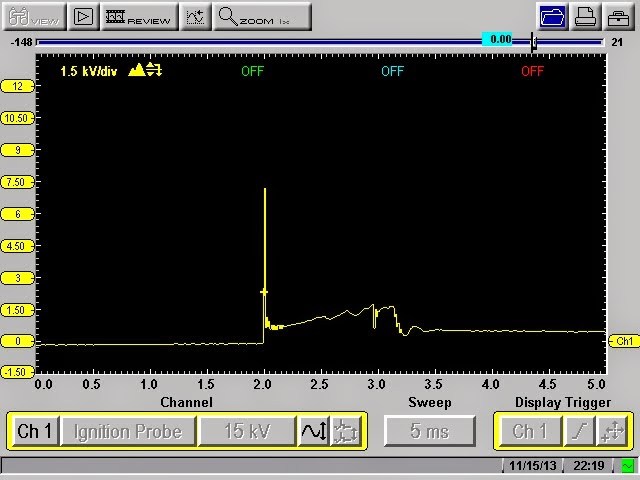
I quickly identify the correct pins at the PCM for crank and cam sensors with my service information and setup my scope. I give it a crank.


Here we have crank sensor in yellow and cam sensor in green. We have nice clean transitions on both sensors. But, something seems odd to me. Let me zoom out a bit.


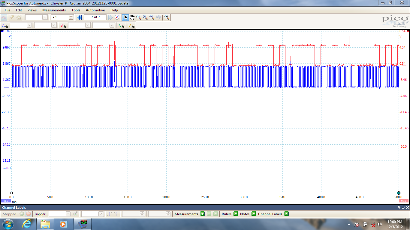
Hmm. I have seen this waveform many times but not a 2002 vehicle. This is where having a known good waveform library comes in handy. I know that I have a known good waveform from a 2002 Jeep Liberty 3.7 Liter in my library. Let's pull it up.


Here again crank sensor in yellow and cam sensor in green. This pattern differs greatly on both crank and cam of my no start Jeep. I am starting to realize what happened here. The pattern I am getting from my no start Jeep is a NGC controller pattern not a JTEC controller pattern. Lets look at them together.


Top pattern is our no start and bottom is my library pattern. NGC controllers didn't come out until 2004 for the most part. So now I ask the hard question. Hey, what year vehicle did this salvage motor come out of? There are a lot of blank looks at this point. Apparently, the salvage yard sold him a later model motor. Well can't we just swap some parts?


Well it is not that easy. The crank trigger wheel is bolted to the crankshaft and then we have the camshaft trigger wheel also to deal with as well. The salvage yard probably had good intentions in selling the shop a later model motor. However, in the long run it was the wrong decision. A correct year motor is the proper answer here.

I will be featuring some more "Frankenstein" vehicles as I like to call them in upcoming posts. I have a ton of them.

I will also be featuring some Pico scope and scope in general posts as well. My buddy Carlos at Aeswave gave me that suggestion and I am only too happy to oblige. Again, I can never say enough about Aeswave.com. They are excellent.

Since purchasing a Pico scope and becoming an "Autonerd" I have to say I have had some great customer support and the techs on the Autonerdz forums have been inviting and top notch. You can never have too many people in this business to bounce ideas off, blow off some steam, or to just chat. No one tech knows it all. We all learn something every day. Some of my lessons I would like to forget.

Remember, if anyone has any suggestions or something you would like to see drop me a line. 

Sunday, March 8, 2015

2004 Chrysler PT Cruiser


This is a 2004 Chrysler PT Cruiser 2.4 Liter Turbo model with 96,158 miles on it. This shop called me in about a week ago to look at a Knock Sensor code. I diagnosed the Knock Sensor code as a bad PCM. The vehicle ran well at that time. I advised the shop a replacement PCM would be needed turn the MIL lamp out and pass the monitors for state inspection. I get a call a week later stating that they went with an online source for the PCM. They ordered this PCM and installed it they had no more Knock Sensor code but had a very poor running vehicle with a misfire. They had some type of "coil" code so they installed a replacement coil pack only to have the misfire and code return pretty much immediately.  No Knock Sensor code returned but the vehicle was running very poorly. He asked me how he should proceed. I advised the shop that if he did not have this poor running and "coil" code with the original PCM that it was either a bad replacement PCM or something happened in between. They called the aftermarket supplier of the replacement PCM and they agreed to have another shipped out. They installed the second replacement PCM and the vehicle ran even worse. At this point they wanted me to have a look.

I arrived at the shop started the vehicle and indeed it ran poorly with a substantial misfire. I pulled a code P2302 code. This code is for coil #1 Insufficient Ionization. This is a very common code on Chrysler vehicles. On this Chrysler style ignition system the ASD (Automatic Shutdown) relay supplies battery power to the positive side of the coil. The voltage flows through the primary windings of the coil out the coil negative terminal back to the PCM. The PCM is the ignition module and responsible for primary triggering. This code sets when it does not see proper primary events. The flowchart for this code is vague at best. I see many reasons for this code. But I always start with a Crankshaft Sensor and Camshaft Sensor scope test looking at the signals and the relationship. This is of particularly great importance on this vehicle. I see timing belt installation errors all the time. On this vehicle timing belt jobs can be challenging. Yes, you can look at cam and crank error in degrees with the scan tool. But, I want to see the raw data.


Here is the scopeshot. Crankshaft Sensor is in blue and Camshaft Sensor is in red with the vehicle running at an idle. What do you think? I think the sensor voltages are nice I see nothing strange. But what about the relationship? This is where building a known good waveform library helps.


Here, I have a saved waveform from a known good vehicle of similar year and motor size. So what are we looking for? Here is what I do.


I pick out something repetitive and telling. In this case I see the falling edge of the Camshaft Sensor pulse after the large pulse lines up with the falling edge of this wide Crankshaft Sensor pulse everytime on my known good. I also see it does the same on my PT Cruiser capture. This is very important without this proper sequencing coil events, injector events, and others can get skewed or fail to happen causing misfires, MIL illumination, no starts, etc. So what's next?


Let's add the primary operation of the portion of the coil that is not flagging the code. I see a nice consistent primary triggering on this wire that triggers the coil that gives spark to the #2 and #3 cylinders. Now, let's have a look at that problem circuit.


I see no primary events at all. In fact it never wavers at all. It stays low all the time. How low? Let's bring in some cursors to measure.


Looks like approximately 600mv. I took these readings right at the coil connector. So what are our possibilities? I could have a grounded circuit, a grounded PCM driver, a bad connection right the coil connector, an open primary circuit in the coil itself. What would be easiest and quickest.


Oh yeah the twenty dollar test light. No LED's, no circuit boards just the old fashioned test light. So here I have the clip end of the test light to battery positive and the point in coil trigger wire for the coil that is operating. No light no ground. Now, let's look at that problem circuit.


Yikes! This circuit is grounded. Next, we need to see if its the wiring or the PCM driver.


Disconnecting the correct PCM connector and the test light goes out. Bad PCM. A further investigation of the coil revealed a bulging blown out coil from getting grounded all the time. I advised the shop owner that the vehicle needs yet another PCM and a new coil. I cautioned the shop owner that these PCM's remanufactured either from Chrysler or aftermarket sources have a high fail rate for problems after remanufacturing. I would recommend new if available. I have been through this more than once where multiple remanufactured PCM's had issues resulting in either a new or even a used units to be installed to get the vehicle repaired properly.

A couple of days later I was back at the shop programming a Chrysler remanufactured PCM (The customer nor the shop wanted to spend for the new unit) and installing a OE coil. Afterwards the vehicle started and ran properly. Thankfully.


Those of you that follow me may have noticed something different on this post. I am using a Pico scope instead of my usual Snap On Modis. The Pico gives me a little bit more versatility for data capture. The Snap On scope products are very good units. Here, I have a section zoomed in. Nice right. Want more zoom.


I am just scratching the surface with this tool. I am learning more about it's capabilities everyday. Looking forward to sharing it with everyone.

Sunday, February 15, 2015

Quick and Dirty


2005 Ford F-150 with 136,471 miles on it. This vehicle has the 5.4 Liter 3 valve engine with VCT (Variable Cam Timing). Shop owner tells me that that the customer is complaining of a rough idle and the Check Engine lamp on. This truck is super clean. I arrive at the shop and indeed it has a rough idle. Seems to improve with rpm. This is my first clue. The title here is "Quick and Dirty". I want the most information in the shortest amount of time.


I run a KOEO self test with my IDS. The vehicle has no on demand codes. But, has quite a few KOEO CMDTC's (Continuous Memory Diagnostic Trouble Codes) commonly referred to as memory codes and a pending code. Let's go through them. The P0012 is very common on these engines. I highlighted it for a reason. With IDS you get a decent code description. As you can see it is an issue with cam timing on bank 1. P0172 is bank 1 rich. P0174 is bank 2 lean. P0301 and P0303 are misfires detected for cylinders #1 and #3. P0316 is a misfire detected at start up.  More clues here. But, let's look at some live data.


I load some pids I want to see on Datalogger on my IDS. I immediately see that bank 1 has issues. At an idle both banks should be near zero degrees for error and advance. Bank 2 is and Bank 1 is not.


Here is another truck I took a snapshot on that was running well. At this point I can also take a look at a couple of other great functions of IDS to get more information.


Here is a live power balance with IDS. Dark blue is where you are and grey is where you have been. It is called a histograph. Cylinder numbers in the vehicles firing order are up top and the green horizontal line represents 0. Below the zero line is a cylinder that is not contributing. The histograph shows cylinders 1, 2, 3, and 4 are below. Cylinders 5, 6, 7, and 8 are above. This is not uncommon to see cylinders following a misfiring rise above the zero line. On a good running vehicle the dark blue line is straight across the green zero line. So now I know that cylinders 1, 2, 3, and 4 are not contributing properly. From the layout of this engine these cylinders are all on Bank1 which is passenger side of the vehicle. I am starting to build my case. One more great test and I think I will be ready to present my case to the shop owner.


This is the relative compression test results. This function with IDS will compare cranking cylinder contribution and compare against each other. It is a great test. The test will automatically suspend injector pulse and prompt you to depress the accelerator pedal all the way down, and prompt you to crank the engine for 10 seconds. As you can see our problem cylinders 1, 2, 3, and 4 have low contribution compared to the others. I usually will investigate if its a 2% difference. We are looking at a much greater difference here. Sometimes, when there are cam timing codes this test can get altered or refuse to run. I did backup this finding with a cranking amperage scope test to confirm.


   Here is vehicle that has no issues. Big difference. At this point I have a pretty good case with either a timing chain issue on bank 1 or a stuck phaser on bank 1. More likely bank 1 chain is off. I see this issue where the tensioner goes bad and leaks internally and doesn't provide proper tension on the chain or bank 1 timing chain guide broke and caused the chain to skip. The other issues that lead me here are the opposing fuel trim codes one side lean and the other side rich. Also, the fact that the misfire improved with rpm. All signatures for a mechanical valve timing issue. I present my case to the shop owner. I can pinpoint it further but would need additional time and diagnostic costs. He refuses at this point until he informs the customer. The customer was figuring on some plugs and coils was going to take care of this unfortunately not. I also discussed with the shop owner the oiling issues with this engine. I always advise my customers not to do any internal engine work on these engines until a thorough manual oil pressure test has been performed with the proper weight and amount of oil. Shops are always surprised when I tell them you need to have a minimum of 20psi hot in gear and the needle should be rock stable. If it does not meet this minimum reading or the needle is erratic the oiling system must be repaired first before repairing other issues. The whole VCT system revolves around proper oil pressure.

Sunday, February 8, 2015

Communication Breakdown


This 2008 Jeep Grand Cherokee with 68,592 miles on it has an issue. The shop owner called me saying that dash gauges, turn signals, power locks, and radio were all inoperative. Furthermore, the dash had every warning lamp illuminated. The vehicle started and ran quite well. I arrived at the shop and sure enough the complaints were verified. I have seen ignition switch issues cause this same set of circumstances before. I checked voltages at a couple of places and quickly ruled that out. It was time to dig deeper.


I hooked up my WiTech system and quickly saw that one whole communication data buss was inactive. The codes I pulled from the FCMCGW (Front Control Module Central Gateway) confirmed what I saw on the topology screen. I needed to check actual voltages on the CAN B buss.


Here is a little network topology layout for this Jeep. Let's review operation. We will start at the FCMCGW. This is the central hub or gateway for both the CAN-C buss and the CAN-B buss. It also translates to a Diagnostic CAN-C buss to the Data Link Connector. Some earlier diagrams will show this as CAN-D for CAN Diagnostic. CAN-C modules are items that need high speed data transmissions for operation such as PCM, TCM, ORC (Airbag Module), etc. This data buss typically is not fault tolerant. In other words if we have a short to power, a short to ground, an open on one wire the buss will be compromised and will not function properly. CAN-B buss has slower speed data transmission and such has "non-essential" modules on its wiring. These include Drivers Door Module, Sunroof, Parking Aid, etc. This buss is fault tolerant. If one wire was open or shorted the modules would continue to operate. Fault codes would be set however. Both CAN-C and CAN-B are two wire twisted lead buss systems. Both buss systems "mix" at FCMCGW. I need to check CAN-B buss voltages. Hmmm, where to check.


My favorite spot and easiest on this platform is under the passenger front seat at the Heated Seat Module. I backprobe with my scope on both CAN-B buss wires at the HSM. I have absolutely no activity. I spared you the scopeshot. I also verified proper power and ground at the HSM. This can play an important factor as well into buss communication. Now, I am left with do I have a wiring issue or a module fault. I go back to my WiTech.


I go into the Loss of Comm Test. This shows all the modules that should be there and if they are reporting. As you can see all the CAN-C modules are reporting as well as the FCMCGW. All of the CAN-B modules are not reporting and more importantly they all have the same number of no responses. I leave my scope leads in at the HSM and disconnect the connector and cycle the key. Still no activity on the buss. I always try the easiest action first. So I know that my HSM is not my issue. I have a communication breakdown. There is a reason I named this post communication breakdown. It is one of my favorite Led Zeppelin songs. When I find myself getting scattered I can always count on the music of Led Zeppelin to get my on track again. So, I go back to my truck get some Zeppelin on and look at a wiring diagram for the CAN-B buss system.


Here is one leg of CAN-B. Something is corrupting the CAN-B buss. That is a lot of modules to disconnect one at a time or wiring to check. I close my eyes and let the voice of Robert Plant carry me away to even me out. What do I always say and preach? Break it down or divide and conquer. I look at the wiring diagram looking for my best course of action. What will give me the best results.


As Jimmy Page belts out yet another one of his signature flawless riffs it comes to me. This C313 will give me possibly four modules if I disconnect it. Ok, now lets look where it is. Service information says it is located left rear of vehicle behind an interior panel. Great. One thing the liftgate is inoperative. Yes, I could pop that panel off and manually unlock it but that is more work. I crawl over the seats and was able to get to the left rear interior panel that hides C313.


I pry it back a bit to uncover C313. I disconnect it and the horn starts going off. Bingo! I jump back out. Hit the remote to shut off the blaring horn and cycle the key.


I am now able to open the liftgate. Here is that panel as viewed from the open liftgate area. My scope reading at the HSM show activity. I go back to the Loss of Comm Test.


Here it is after disconnecting C313. Now, the only non reporting modules are the Sunroof and the EOM (Overhead Console). All functions are restored save the Sunroof and EOM. I inform the shop owner that further diagnostics would require dropping the headliner to disconnect said modules and inspect wiring to the modules. I am leaning heavy to a bad Sunroof module. The shop owner then tells me that last summer this vehicle had issues with sunroof drains clogging. At this point the shop owner also advises me to leave C313 disconnected until he asks the customer if they want to go further. Apparently, the customer just called and their other vehicle broke down that morning and they are without a vehicle and need a vehicle desperately. I pull out of the shop with the sounds of Led Zeppelin pouring through my speakers. Hey Hey What Can I Do.

Sunday, February 1, 2015

Mailbag

I get quite a few private emails asking for advice or problems concerning a vehicle. Rather than answering them privately I will answer them online so we can all benefit. I will display the email in full as it was sent but I will not disclose the senders email address. Just in case they want to be anonymous. Please realize I get email from all over the world so sometimes spelling and sentence structure may not be perfect. Cut them some slack.  Here are a few. My answer will be in blue writing.


Hi i am a technician that reads your blog with great anticipation , i recently had a 05 max semuler to your 06 maxima you covered in your 2015 January blog came into the shop running and then would not start for nothing with the same symptoms .  Customer would not go no further with the reapers or diagnostics but i feel pretty sure it was the seem problem . You make it look so easy  ,  if you had to choose between diagnostic equipment , training , information what would you chose why and in what order and thank you so very much looking forward to the next one , just wondering have you considered videos sometimes and thanks again you are the man .

Thank you for reading. I really enjoy getting feedback from the people who read it. Believe me it is not easy. You see after it has been processed and written up. Plus, after the repair has been made it always looks easy and logical. I get my butt kicked just like every other tech. I always look at it as a learning experience. Even though when I am in the heat of the moment I don't think that way. 

On to your question about choices. I would not be able to choose between the three. They intertwine and are dependent on each other. You need diagnostic equipment. But, you also need training to use the equipment to it's full potential. You definitely need accurate current information to repair vehicles today. There is so much that you can't memorize information. I think a blend of the three along with dedication by the technician equals a successful career. You have to be willing to put in the time to excel in this industry. You have to ask "Why did that happen?" instead of "I don't care".

I have considered videos. Anyone that knows me will tell you I am better in real life. I am a very animated and demonstrative person. Maybe, I will have to start my video career. As far as me being the man. Thank you. But, I am just one of many dedicated, intelligent, and caring technicians in this industry. There are many "Men" and some "Women" as well. 


Am an automobile technician. I have a 2000 Pathfinder that won't start. There's spark on the plugs and there's good pressure on the fuel pump. I scanned it and got the P1320 code. Pls what do I do?   


Well this can go many ways here. Let's start with the P1320 code. The P1320 in it's self usually doesn't cause a no start. Now let' examine your testing. You say you have spark. How are we measuring that? Are you using a scope? Screwdriver? I would recommend what I call my $14.00 scope. This is an adjustable spark tester that you unscrew to create an air gap. Not a bulb type tester. They are on any tool truck. Get one and unscrew it out to 30KV which is approximately 3/4 of an inch. Now do we have bright white consistent spark while cranking? Then we have to talk about whether we are getting spark at the proper time. That can get a little involved. Many methods from simple to hi tech.

Good pressure on the pump. What was the pressure?  Did we use a gauge? Or did we use the calculation of how far the fuel shot out in feet to pressure calculation? I am kidding on that last one. Where did we put the gauge? In place of the fuel filter, inline or "deadheaded" on the end of the pressure line. This placement will make a big difference. But, hey lets make it simple and fast. If we spray some good quality carburetor spray in the throttle body and crank it over does it kick? Want to start? Or nothing? Are the plugs coming out wet or dry?  

Was there any recent work done to the vehicle. When was the last time the vehicle started? Is the fuel stale? Injectors glazed over from rotten fuel? What kind of tooling do we have at our disposal? These are all factors to consider. Start with spark quality and then see if it wants to kick on carburetor spray. Keep us posted and I am sure we can get your Pathfinder rolling again or give it a proper burial. 


Sunday, January 18, 2015

Work smarter not harder


I get a call from a shop owner. He explains he had this 2002 Mitsubishi Montero Sport 3.0 liter towed in for a no start. They found a broken timing belt. He explained to the customer that the timing belt broke and there may be valve damage from the broken timing belt. Some engines are interference and others are non interference. Another factor to consider here is the vehicle is being towed in as a no start. The shop has no way of knowing how the vehicle ran prior to the timing belt breaking. The customer gives the okay for the timing belt replacement. The timing belt is replaced and the vehicle starts but runs poor. It has a very rough idle and a misfire. Now, the shop owner is wondering is the timing belt installed right? Are there further issues? He calls me and wants me to check it out. I arrive at the shop and the vehicle starts and definitely runs poor with a misfire. Now, I need to give you some setup on my next step.


Here is my high amp probe. It has a 600 amp capacity. It is different from my low amp probe in its capacity and scaling. Basically, with this probe 1mv equal 1 amp. It's large jaw capacity is a necessity for the next test I want to perform. I want to check compression on this vehicle. I don't want to spend all day taking spark plugs out and on this vehicle removing the upper intake to gain access to half the spark plugs. We are going to do a relative compression test. It is one of my favorite tests. Easy to do and packed with information. This test will measure the amount of electrical current needed to turn the motor over as it relative to each cylinder. What we are looking for is uniformity between cylinders. We are also looking for a proper cranking amperage as well.


To perform this test I disable fuel accordingly. You want no fuel flowing into the cylinders and washing them down giving you inaccurate testing.  Then I setup my scope with amp probe around a battery cable with the arrow on the clamp in direction of current flow. Then we are going to crank the engine over, record, and analyze the results. A couple of key points here. You must have a good battery and starting system. No battery chargers. A jump box is acceptable. A donor battery is sometimes needed if the vehicles battery wont support 20-30 seconds of cranking. Lets give it a crank.

 
Here we have some cranking time on the screen. What we are looking for is uniformity. We are also looking for about 150 cranking amps and about 30-40 amp differential between high and low points. We have about 4000ms of time which is 4 seconds. I see something that stands out.


I zoomed in a bit here and highlighted what I saw. Every sixth pulse is low. The pulses are representative of our six cylinders. We have about 150 amps and approximately 30-40 amps from high to low. Now, we know we have a cylinder that has substantially lower compression due to the low amperage load to "turn" that cylinder. The next cylinder after a low cylinder will usually be a higher amperage load as it "catches up" so to speak. Ok, so we know we have a low cylinder. But, which one?

 
Our next tool is an ignition synch probe. This will go around an ignition wire and will display a pattern when spark is flowing through the ignition wire. This pattern will not be detailed like a true blue ignition probe but all we are looking for is a reference here.


I place the probe around number one ignition wire. Crank the engine over again. The shop left the timing belt covers off here.


Now, we have some reference to work with. The large green spikes are cylinder number one firing. Most vehicles will crank somewhere near TDC so the spark spike should split the relative compression spike right in the middle. That looks good here. Now we can find out our low cylinders identity. Let's mark it up.

 First, we need to identify firing order. I also use this diagram to verify where cylinder number one is. Always consult the service information. If in doubt reference several sources. We need to be sure.


I marked it up with the firing order. Now we can definitely say that cylinder number 3 is not happy. Do we have a hole in the piston, a valve not seating, a broken valvetrain component? Well we really can't say from this. But, we saved about 2 hours of labor. In 15 minutes we are here and the most labor we did was to disable the fuel system. I do a couple of more tests before talking to the shop owner.


 I scope crankshaft and camshaft sensors to see if the timing belt is correctly installed. Typically, if the timing belt was incorrectly installed it wouldn't affect one cylinder it would be multiple cylinders. But, it only takes a minute.


I compare our pattern to the service information and it looks dead on. Please note that service information is different than my scope pattern as far as placement of signals. The service information has the crank sensor pattern on top where as I have it on the bottom. I always put my crankshaft sensor pattern on the bottom and I always use channel 1. It is the OCD coming through.


I look at the ignition pattern on a known good cylinder. In this case it is cylinder number one. We have about a 7.5 KV spike and noticeable cylinder turbulence in the firing line. This cylinder is working. Lets look at cylinder number 3.


Here is our bad cylinder low 3KV spike, a long firing line, and no turbulence at all. This cylinder is not contributing. It is like its firing the plug in the atmosphere instead of a combustion chamber. I inform the shop owner of the correct timing belt installation and the low number 3 cylinder. I advise him that from here we can do a leakdown test or I can use a pressure transducer in the cylinder coupled with a vacuum waveform to pinpoint the issue. He tells me he will take it from here. Cylinder three is accessible without taking the upper intake off. The whole idea here is to work smarter not harder. The tooling used here is within the reach of most techs.