Sunday, March 20, 2016

Wiring and Connections

In my daily travels to shops I get to see some interesting issues. I uncover some interesting wiring issues daily. Some are natural and some are natural with some human help so to speak. I used my human senses and brain power more than my other test equipment to find these issues

One of my really good customers calls me to tell me he has a 2008 Ford F250 that has an intermittent no crank condition and the customer reports that when the vehicle is in this no crank condition the dashboard has all the warning lamp illuminated.

I arrive and the truck starts and runs like clockwork. This happens all the time. I scan all the modules with Ford IDS and there are many communication codes dealing with the CAN (Controller Area Network) network. A quick scope check tells me the CAN network is operational right now. I look at the modules involved. I see that the CAN wiring runs throughout the vehicle. I give a visual under the hood for anything rubbing or a harness that is not secured. Looks pretty good. I then see the CAN wiring runs down each rocker panel. This truck is definitely a typical Northeast plow truck work horse. I pull up the passenger side sill plate.


Yikes! There is dirt, leaves, and not too much left as far as the rocker panel itself. I literally dig out the wiring harness and surprisingly it is in good shape. I cannot find anything wrong. Well if this side is like this what does the other side look like?


 Just as bad if not worse. I can immediately duplicate the issue as well by moving the harness. You can see the issue barely in this photo. Lets get closer.


Here it is. Between the water intrusion and the dirt it wore one of the CAN wires and corroded it. I repaired this wire and a couple of others. I advised the shop to vacuum out both side sill plate areas. Unfortunately, this will happen again due to the rocker panel area being rotted. The fact that the customer likes to run this vehicle into mud up to the doors multiple times doesn't help at all either.

Next up is a 2012 Toyota Camry that is at a body shop. The owner of the shop tells me that the vehicle was actually in an accident a couple of weeks ago and was repaired at another shop a couple of hundred miles away. Recently, it has developed a couple of strange issues. The vehicles cooling fan runs all the time, headlamps illuminate when not requested, and most troubling is the vehicle will start on its own and won't shut off! The car owners insurance suggested this body shop to rectify the situation. That is when he called me in.

I have been down this road before with these vehicles. In fact there is a TSB from Toyota concerning this issue. I printed it out ahead of time so I could give it to the body shop. I arrive at the shop and the shop owner is reviewing the issues with me. I pop the hood remove the cover from the underhood fusebox and I am greeted by the unmistakable smell of burnt electronics. As the owner is talking to me I wiggle up the Integration Relay in the underhood fusebox.


That is a hole burnt right through! Now the whole shop has the burnt electronics odor emanating throughout. The body shop owner lets out a couple of descriptive expletives and calls everyone over to look at the relay. Next lets look at the wiring.


That bare wire in the photo is not supposed to be bare. The heat from the amp load burnt off the insulating jacket and left a bare conductor. The reason is carefully laid out in the TSB. The vehicle grounds are attached to a support. Typically, a body shop will undercoat or paint these supports and often times insulate the grounds causing a voltage drop. The TSB wants you to expose the support sand and use new redesigned bolts. But, we will still need a underhood fusebox, some wiring, and a new Integration Relay. I leave the TSB with the body shop to use as a guide.

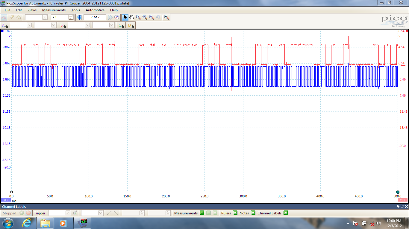
Next is a 2004 Dodge Ram Truck that the owner said just died out and now is a crank and no start. The shop checked for PCM communication and had none. They also check for spark and had none. I arrive and confirm the no communication with the PCM. I check for proper 5vref and have a strange fluctuating voltage that never reaches 3.0 volts. Ok, maybe I have a sensor that is loading the 5vref line down. This is pretty common. A couple of minutes later all sensors on the 5vref line have been disconnected and I still don't have a solid 5vref. Lets check powers and grounds at the PCM. I pull a wiring diagram and verify proper powers and grounds. Did this PCM go bad? Looking that way. I have been burnt before with JTEC terminal tension. I pull the PCM connectors to do a pin drag test and quickly see my issue.


That green spot is supposed to be a terminal. A terminal that supplies power to the PCM. Where is the terminal?


There it is stuck in the PCM connector. Now, this vehicle is going to need a PCM and I am going to have to do some micro surgery on the PCM connector and replace that terminal. The terminal that rotted is at the bottom of the PCM. Somehow, water got into the PCM harness and laid there and rotted that terminal out. In talking to the owner this vehicle was in an accident years ago and sat for a long time before he bought the truck. probably with the hood off. Maybe then?  

I have had quite a few emails lately. I will be answering them all real soon.

Sunday, February 14, 2016

2000 Nissan Maxima


One of my shops calls me and says that they have a 2000 Nissan Maxima and its a crank no start. I arrive the next day and I see a very clean Maxima with 75,627 miles on it. I reach in and it cranks strong with a good cadence. But, it doesn't even hint of starting. Time to get some information. I quiz the shop owner who tells me the vehicle belongs to a gentleman that spends extended time out of the country at times. He left six months ago and the vehicle was running. Ok, now we have some information. Right away I am thinking rodent damage. Mice and the like love to crawl up into vehicles and chew on wiring. I perform a thorough visual inspection and no obvious signs of rodent damage.
I hook up my scan tool and check for codes and I have a P0335 code for Crankshaft Position Sensor. I also have no cranking rpm on my scan tool when I am physically cranking the engine over. Now at this point some background on this system. This Nissan platform is very common in my area and I have a lot of experience with these vehicles. This year Maxima has a CKP (POS) that reads off the flywheel and is mounted in the oil pan adapter. A CKP (REF) that reads off the front crankshaft dampener. A CMP (Phase) that reads off the Bank 2 Camshaft gear. This setup described is for a 3.0 Liter VQ30DE engine. Now there are some variables. There are two different crankshaft dampener setups. This will alter the CKP (REF) signals. I forget the years off the top of my head that are different. I have many known good patterns from many years on this platform. I just compare to a know good in my library of waveforms.
Typically, if any these sensors are not reading or reading correctly you will get a crank no start. There have also been issues with grounds, revised starter motors, starter motor RFI while cranking, Usually when there is a ground or starter or RFI issue the vehicle will crank erratically almost like a vehicle with a wet distributor cap. This vehicle cranks smooth. Furthermore, I have seen timing chain issues cause a P0335 no start. Time to hook up the scope.

  
So, here is the a shot of this vehicle cranking with the Pico scope hooked up. This is just a saved screenshot. With the Pico I can save a file with a tremendous amounts of data. Furthermore, I can manipulate the file how I wish afterwards. So what I see here is the correct CKP (REF) pattern for this year and it looks like the CKP (REF) and CMP (Phase) are in proper alignment. What I see wrong is an almost non existent CKP (POS) signal. The CKP (POS) is a hall effect square wave signal where the REF and Phase are inductive AC voltage signals. With this I test powers and grounds at the CKP (POS) connector. All good there. Has to be a bad POS sensor. But, how did a sensor go bad in six months of sitting? I always recommend an OE sensor but due to time constraints an aftermarket sensor was ordered. I installed the sensor as the shop owner was busy and went to fire it up and still no start and this time I didn't see any activity on the POS sensor signal now. Sorry, don't have the scopeshot. I was to busy cursing and screaming. I took a breath and popped the aftermarket sensor out and waved a knife blade across the tip of the sensor with the key on simulating the flywheel teeth and saw nothing on my scope. I reinstalled the original sensor and repeated the knife blade test and had activity. I had a theory now.

    
The sensor mounts to the aluminum oil pan adapter. I made sure there was no obstructions first. This time around I noticed quite a bit of oxidation in the POS sensor mounting area. I grabbed some sandpaper and scrubbed the area thoroughly. Hit the the area with a little brake clean and popped the original sensor back in. I hit the key.


The vehicle roared to life and ran well. Now, I had POS signal. Let's zoom in a bit.


Let's zoom in even more. The Pico has excellent zoom and resolution qualities.


Now, you can see the POS signal clearly. I tried the vehicle several times it always started very crisply and the waveform was excellent throughout the temperature ranges. I cleared the code,


Here is the actual piece of sandpaper I used with the oxidation on it. The fastener in the picture is one of the screws that hold the cover on underneath the vehicle. The theory here is that the vehicle sat and the oxidation occurred forcing the sensors air gap to increase. I have seen this before on Nissan vehicles with ABS wheel speed sensors. The aftermarket sensor was bad right out of the box. Having worked with these type of sensors in a lab setup I have seen the slightest change in air gap mean the difference between a signal and no signal. Reminds me of a Maxima I checked out a couple of  years ago for a shop that was a crank no start after an engine replacement. Long story short the shop never swapped the manual transmission oil pan adapter that came with the used engine (where the CKP (POS) mounts) to the vehicles automatic transmission one. The result no CKP (POS) signal because the sensor was too far away. That shop never made that mistake again.

Monday, February 8, 2016

Mailbag


Have received some emails lately. Here is one from Charles Smith.

Title: 2003 Chrysler PT Cruiser P02302

Working on a friend's car, someone else has already changed the plugs, wires, coil and cam sensor. Misfires on cyl. 2 after warm up. But still getting a good spark from coil on 2. Turning off the key and restarting, Engine runs good again for a short time. I'm thinking the pcm has a bad quad driver and is shutting down the injector. What are your thoughts. I'm leaning towards a pcm replacement.

Actually this is a P2302 not a P02302 just to get logistics correct. P2302 is a Coil #1 Insufficient Coil Ionization code. This is a very common code with Chrysler products. The poster didn't leave a VIN or description of engine size or turbo or non-turbo. Either way these vehicles utilize a coil pack design. There is actually two coils so to speak in the one pack. Coil #1 fires cylinders #1 and #4 and Coil #2 fires cylinders #2 and #3. The PCM contains an algorithm that can infer monitored burn time of the secondary pattern to set this code.

A couple of observations. The poster states that it has a misfire on cylinder #2. Yet, the code is for Coil #1 which is cylinders #1 and #4. P2305 would be the Ionization code for Coil #2 which is cylinder #2 and #3. I have seen some cheaper aftermarket scan tools give incorrect codes and code definitions.

When the poster says "good spark". What are we talking about? How are we testing? Scope? Test plug? Adjustable gap style tester? How long it takes for his hand to stop tingling? We need some specifics here. Any late model ignition system should be able to jump a 7/8" gap with a nice white blue consistent spark. 

The poster states someone else changed various parts. Were they OE? I am a big believer in OE ignition parts especially on Chrysler products. There is a difference. I open up the hood on some of these problem vehicles I look at and it looks like the local auto parts chain store threw up into it. When I tell the shop its has a bad coil I usually get "It's new". I tell him/her new doesn't mean good.

Turning off the key and it runs well again for a short time. The PCM is taking out injector pulse when it sees a catalyst damaging misfire on that cylinder. This is perfectly NORMAL. It will discontinue operation for that key cycle. What the poster is experiencing is normal strategy. Fix the misfire and the injector pulse will continue uninterrupted.

Quad drivers is an old GM expression back in 80's when we had quad driver codes. Some Saturn vehicles used quad drivers into the 2000's. This would be a regular driver.

My recommendation to this poster is to recheck codes with a professional scan tool. Replace said replaced parts with OE parts for starters. If it still acts up then we would have scope the primary and secondary patterns. A thorough harness check. There is a very good chance that the PCM is at fault. Usually from degraded secondary ignition components. Now, if we have to go with a replacement PCM. Well, that is always an adventure with remanufactured units. Look at some of my posts. 

Charles, let me know how you make out and if I can help you out anymore.

Monday, January 4, 2016

Off The Grid

Yes, it has been some time since I have posted. I have been super busy and been neglecting my blog. I promise to have some more content up very soon.

In the meanwhile. I just want to wish a very Happy New Year to my crew throughout the country. Those of us that battle problem vehicles on a daily basis. I wish nothing but the best for the coming year. I am grateful to be surrounded by some very good people in the industry from all over the United States and Canada.

Speaking of good people I want to take a moment to acknowledge a good friend of mine Dave Macholz. Dave is an automotive instructor at Suffolk County Community College. He recently has received a very well deserved promotion. The automotive program he is involved in is top notch and will only get better with him steering the way. In addition Dave has been writing in the trade magazines and is a training instructor for WorldPac. Having attended a Toyota class Dave did last month I can attest to the quality Dave is presenting. Hopefully, in the next couple of months Dave and I can collaborate on some local training.

Also take a look at my buddy Mike's website www.advancedmobilediagnostics.com

Mike and I work the same region and sometimes the same shops. We respect each other and each others business. We talk to each other every day and bounce ideas off of each other often. Never can have enough good people that is for sure.


Be back soon
  

Thursday, April 9, 2015

Square Peg Round Hole


I get a call from a shop that uses me regularly. He has this 2002 Jeep Liberty with 127,629 miles with a 3.7 Liter motor. He just swapped a salvaged motor in it and now it doesn't start. This shop does a lot of motor swapping. Every time I go to this shop there seems to be some type of motor being swung in and out. I arrive at the shop and do a quick visual on the installation. I crank the vehicle over and it doesn't start at all. Not even an attempt. Where to start.


I decide to start with making sure we have the right PCM in the vehicle. This is a shot of the module info with the DRB-3 scan tool.  Looks good so far. Notice that this is a JTEC controller. This will be important later on. I also looked at my scanned KOEO values and all looked normal. I checked my scanned crank sensor and cam sensor values while cranking and they were erratic. I really don't trust scanned values for crank and cam signals. I want to see them in real time.


I quickly identify the correct pins at the PCM for crank and cam sensors with my service information and setup my scope. I give it a crank.


Here we have crank sensor in yellow and cam sensor in green. We have nice clean transitions on both sensors. But, something seems odd to me. Let me zoom out a bit.


Hmm. I have seen this waveform many times but not a 2002 vehicle. This is where having a known good waveform library comes in handy. I know that I have a known good waveform from a 2002 Jeep Liberty 3.7 Liter in my library. Let's pull it up.


Here again crank sensor in yellow and cam sensor in green. This pattern differs greatly on both crank and cam of my no start Jeep. I am starting to realize what happened here. The pattern I am getting from my no start Jeep is a NGC controller pattern not a JTEC controller pattern. Lets look at them together.


Top pattern is our no start and bottom is my library pattern. NGC controllers didn't come out until 2004 for the most part. So now I ask the hard question. Hey, what year vehicle did this salvage motor come out of? There are a lot of blank looks at this point. Apparently, the salvage yard sold him a later model motor. Well can't we just swap some parts?


Well it is not that easy. The crank trigger wheel is bolted to the crankshaft and then we have the camshaft trigger wheel also to deal with as well. The salvage yard probably had good intentions in selling the shop a later model motor. However, in the long run it was the wrong decision. A correct year motor is the proper answer here.

I will be featuring some more "Frankenstein" vehicles as I like to call them in upcoming posts. I have a ton of them.

I will also be featuring some Pico scope and scope in general posts as well. My buddy Carlos at Aeswave gave me that suggestion and I am only too happy to oblige. Again, I can never say enough about Aeswave.com. They are excellent.

Since purchasing a Pico scope and becoming an "Autonerd" I have to say I have had some great customer support and the techs on the Autonerdz forums have been inviting and top notch. You can never have too many people in this business to bounce ideas off, blow off some steam, or to just chat. No one tech knows it all. We all learn something every day. Some of my lessons I would like to forget.

Remember, if anyone has any suggestions or something you would like to see drop me a line. 

Sunday, March 8, 2015

2004 Chrysler PT Cruiser


This is a 2004 Chrysler PT Cruiser 2.4 Liter Turbo model with 96,158 miles on it. This shop called me in about a week ago to look at a Knock Sensor code. I diagnosed the Knock Sensor code as a bad PCM. The vehicle ran well at that time. I advised the shop a replacement PCM would be needed turn the MIL lamp out and pass the monitors for state inspection. I get a call a week later stating that they went with an online source for the PCM. They ordered this PCM and installed it they had no more Knock Sensor code but had a very poor running vehicle with a misfire. They had some type of "coil" code so they installed a replacement coil pack only to have the misfire and code return pretty much immediately.  No Knock Sensor code returned but the vehicle was running very poorly. He asked me how he should proceed. I advised the shop that if he did not have this poor running and "coil" code with the original PCM that it was either a bad replacement PCM or something happened in between. They called the aftermarket supplier of the replacement PCM and they agreed to have another shipped out. They installed the second replacement PCM and the vehicle ran even worse. At this point they wanted me to have a look.

I arrived at the shop started the vehicle and indeed it ran poorly with a substantial misfire. I pulled a code P2302 code. This code is for coil #1 Insufficient Ionization. This is a very common code on Chrysler vehicles. On this Chrysler style ignition system the ASD (Automatic Shutdown) relay supplies battery power to the positive side of the coil. The voltage flows through the primary windings of the coil out the coil negative terminal back to the PCM. The PCM is the ignition module and responsible for primary triggering. This code sets when it does not see proper primary events. The flowchart for this code is vague at best. I see many reasons for this code. But I always start with a Crankshaft Sensor and Camshaft Sensor scope test looking at the signals and the relationship. This is of particularly great importance on this vehicle. I see timing belt installation errors all the time. On this vehicle timing belt jobs can be challenging. Yes, you can look at cam and crank error in degrees with the scan tool. But, I want to see the raw data.


Here is the scopeshot. Crankshaft Sensor is in blue and Camshaft Sensor is in red with the vehicle running at an idle. What do you think? I think the sensor voltages are nice I see nothing strange. But what about the relationship? This is where building a known good waveform library helps.


Here, I have a saved waveform from a known good vehicle of similar year and motor size. So what are we looking for? Here is what I do.


I pick out something repetitive and telling. In this case I see the falling edge of the Camshaft Sensor pulse after the large pulse lines up with the falling edge of this wide Crankshaft Sensor pulse everytime on my known good. I also see it does the same on my PT Cruiser capture. This is very important without this proper sequencing coil events, injector events, and others can get skewed or fail to happen causing misfires, MIL illumination, no starts, etc. So what's next?


Let's add the primary operation of the portion of the coil that is not flagging the code. I see a nice consistent primary triggering on this wire that triggers the coil that gives spark to the #2 and #3 cylinders. Now, let's have a look at that problem circuit.


I see no primary events at all. In fact it never wavers at all. It stays low all the time. How low? Let's bring in some cursors to measure.


Looks like approximately 600mv. I took these readings right at the coil connector. So what are our possibilities? I could have a grounded circuit, a grounded PCM driver, a bad connection right the coil connector, an open primary circuit in the coil itself. What would be easiest and quickest.


Oh yeah the twenty dollar test light. No LED's, no circuit boards just the old fashioned test light. So here I have the clip end of the test light to battery positive and the point in coil trigger wire for the coil that is operating. No light no ground. Now, let's look at that problem circuit.


Yikes! This circuit is grounded. Next, we need to see if its the wiring or the PCM driver.


Disconnecting the correct PCM connector and the test light goes out. Bad PCM. A further investigation of the coil revealed a bulging blown out coil from getting grounded all the time. I advised the shop owner that the vehicle needs yet another PCM and a new coil. I cautioned the shop owner that these PCM's remanufactured either from Chrysler or aftermarket sources have a high fail rate for problems after remanufacturing. I would recommend new if available. I have been through this more than once where multiple remanufactured PCM's had issues resulting in either a new or even a used units to be installed to get the vehicle repaired properly.

A couple of days later I was back at the shop programming a Chrysler remanufactured PCM (The customer nor the shop wanted to spend for the new unit) and installing a OE coil. Afterwards the vehicle started and ran properly. Thankfully.


Those of you that follow me may have noticed something different on this post. I am using a Pico scope instead of my usual Snap On Modis. The Pico gives me a little bit more versatility for data capture. The Snap On scope products are very good units. Here, I have a section zoomed in. Nice right. Want more zoom.


I am just scratching the surface with this tool. I am learning more about it's capabilities everyday. Looking forward to sharing it with everyone.

Sunday, February 15, 2015

Quick and Dirty


2005 Ford F-150 with 136,471 miles on it. This vehicle has the 5.4 Liter 3 valve engine with VCT (Variable Cam Timing). Shop owner tells me that that the customer is complaining of a rough idle and the Check Engine lamp on. This truck is super clean. I arrive at the shop and indeed it has a rough idle. Seems to improve with rpm. This is my first clue. The title here is "Quick and Dirty". I want the most information in the shortest amount of time.


I run a KOEO self test with my IDS. The vehicle has no on demand codes. But, has quite a few KOEO CMDTC's (Continuous Memory Diagnostic Trouble Codes) commonly referred to as memory codes and a pending code. Let's go through them. The P0012 is very common on these engines. I highlighted it for a reason. With IDS you get a decent code description. As you can see it is an issue with cam timing on bank 1. P0172 is bank 1 rich. P0174 is bank 2 lean. P0301 and P0303 are misfires detected for cylinders #1 and #3. P0316 is a misfire detected at start up.  More clues here. But, let's look at some live data.


I load some pids I want to see on Datalogger on my IDS. I immediately see that bank 1 has issues. At an idle both banks should be near zero degrees for error and advance. Bank 2 is and Bank 1 is not.


Here is another truck I took a snapshot on that was running well. At this point I can also take a look at a couple of other great functions of IDS to get more information.


Here is a live power balance with IDS. Dark blue is where you are and grey is where you have been. It is called a histograph. Cylinder numbers in the vehicles firing order are up top and the green horizontal line represents 0. Below the zero line is a cylinder that is not contributing. The histograph shows cylinders 1, 2, 3, and 4 are below. Cylinders 5, 6, 7, and 8 are above. This is not uncommon to see cylinders following a misfiring rise above the zero line. On a good running vehicle the dark blue line is straight across the green zero line. So now I know that cylinders 1, 2, 3, and 4 are not contributing properly. From the layout of this engine these cylinders are all on Bank1 which is passenger side of the vehicle. I am starting to build my case. One more great test and I think I will be ready to present my case to the shop owner.


This is the relative compression test results. This function with IDS will compare cranking cylinder contribution and compare against each other. It is a great test. The test will automatically suspend injector pulse and prompt you to depress the accelerator pedal all the way down, and prompt you to crank the engine for 10 seconds. As you can see our problem cylinders 1, 2, 3, and 4 have low contribution compared to the others. I usually will investigate if its a 2% difference. We are looking at a much greater difference here. Sometimes, when there are cam timing codes this test can get altered or refuse to run. I did backup this finding with a cranking amperage scope test to confirm.


   Here is vehicle that has no issues. Big difference. At this point I have a pretty good case with either a timing chain issue on bank 1 or a stuck phaser on bank 1. More likely bank 1 chain is off. I see this issue where the tensioner goes bad and leaks internally and doesn't provide proper tension on the chain or bank 1 timing chain guide broke and caused the chain to skip. The other issues that lead me here are the opposing fuel trim codes one side lean and the other side rich. Also, the fact that the misfire improved with rpm. All signatures for a mechanical valve timing issue. I present my case to the shop owner. I can pinpoint it further but would need additional time and diagnostic costs. He refuses at this point until he informs the customer. The customer was figuring on some plugs and coils was going to take care of this unfortunately not. I also discussed with the shop owner the oiling issues with this engine. I always advise my customers not to do any internal engine work on these engines until a thorough manual oil pressure test has been performed with the proper weight and amount of oil. Shops are always surprised when I tell them you need to have a minimum of 20psi hot in gear and the needle should be rock stable. If it does not meet this minimum reading or the needle is erratic the oiling system must be repaired first before repairing other issues. The whole VCT system revolves around proper oil pressure.