Sunday, February 23, 2014

Seeing double vision-Part 1


This winter has been brutal here in the Northeast. It makes everything harder. So here is a little something to warm you up. Well it is more like warming oxygen sensors up. Lets talk oxygen sensor heaters. Here is a very popular vehicle. This 2008 Jeep Wrangler with 50,731 miles and a 3.8 liter in it has a MIL lamp on. The shop tells me he is getting O2 sensor heater codes that come right back immediately after clearing. He has tried some new O2 sensors and still has issues. Lets take a look at the codes.
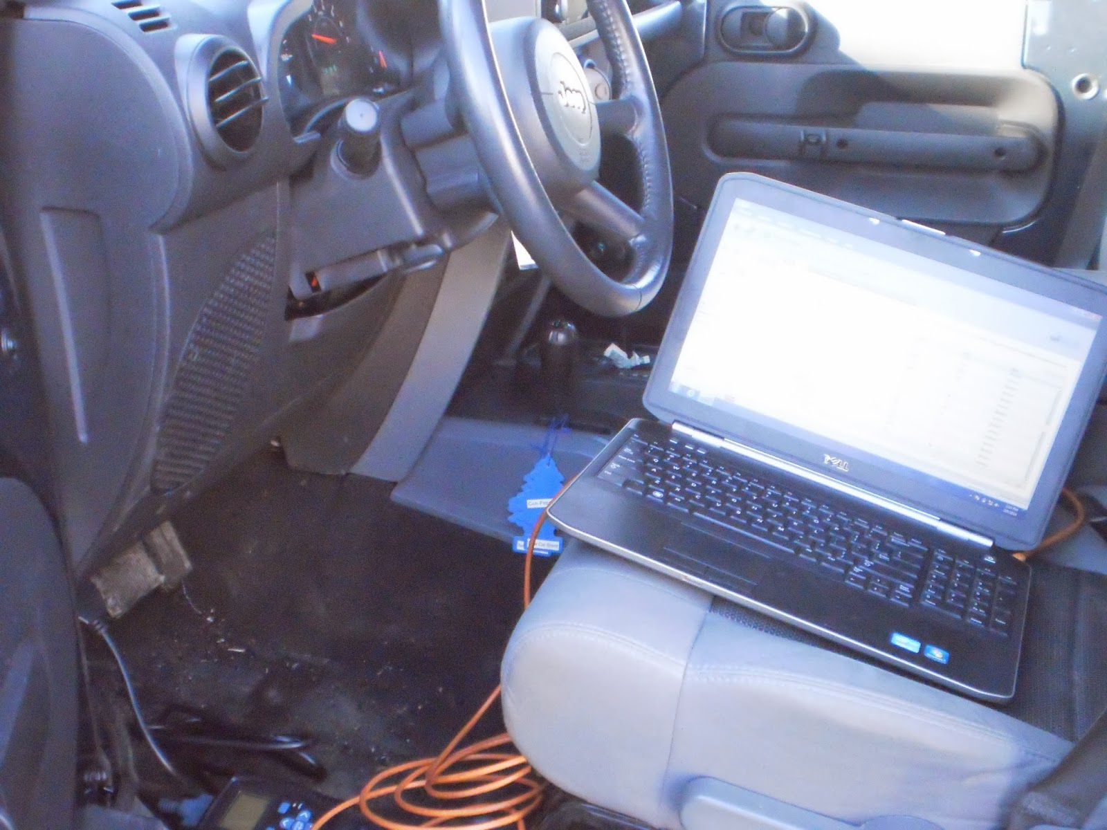

I always do a quick visual before hooking up my scantool. Lets pull the codes.


I am using the factory scan tool WiTECH. I see O2 heater codes for all four O2 sensors and they are active. Active meaning the fault is there right now. As opposed to stored where the fault happened some time ago but is not occurring right now. Now when I see all four O2 codes I immediately think of two issues. One being wiring and the other being the PCM itself. If this vehicle was flagging one O2 heater code it is feasible that it may be the sensor itself. A couple of important notes. These vehicles do not seem to tolerate aftermarket oxygen sensors. It is always better to go with an OE sensor. The other is that the O2 heater is a learned value. A bad oxygen sensor may cause a heater code and after replacement it may still flag a heater code. A PCM reset is in order after sensor replacement. The easiest/most definitive way is to disconnect a battery cable for 10 minutes or so. Back to the situation at hand. Lets look at the circuit.


What is a little unusual on Chrysler NGC O2 heater circuits is that the heater element is grounded all the time and the PCM (NGC Controller) pulses 12 volts to light up the heater. Typically on a cold motor the PCM will duty cycle the heater more and then lessen duty cycle as the vehicle warms up. It is all in an effort to get that vehicle in to a closed loop/feedback situation as quickly as possible. In the automotive world it all revolves around CAFE (Corporate Average Fuel Economy). I want to test
this circuit.


I want to check the circuit dynamically and statically. I first locate pin locations at the PCM. In this case Bank 2 Sensor 1 heater circuit is at terminal #17 at the PCM connector with the orange insert. Lets hook up.


I backprobe the wire here and also I am going to put a low amp probe around this wire as well. I want to see the PCM actuate the heater and what kind of amperage we have on the heater circuit.


But, first lets look at some data. What does the PCM think. As you can see here the PCM is not actuating the heaters. They are at 0%. Look at the O2 heater temp pids. Strange, right? This is a calculated value that the PCM formulates through an algorithm programmed into the PCM. Well if the PCM will not work the circuit, how can we?


Using WiTECH or a full function scan tool we can actuate the heater circuits in increments up to 25% on this application. Lets get the scope on there.


Here is Bank 2 Sensor 1 heater circuit. What I am looking for is a one to one relationship between actuation and amperage. Clean transitions and proper amperage. Looks good so far. This is a dynamic test. This test is done key on engine off. Looking at the amperage and using Ohms Law we can figure out our heater resistance as well. On time is our 25% commanded. Lets look at Bank 1 Sensor 1 heater circuit.

 
More of the same here. At this point my static testing will be academic. But lets do it anyway.


I am testing static O2 heater resistance. One lead is in the PCM connector and the other is to ground.
Remember what I said about figuring out heater resistance with the voltage and  amperage scope shot. Well here you go we were pulling just under an amp. 12 volts with a 14 ohm load nets you about .85amps. The downstream O2 heater circuits are on a different PCM connector.


Upstream and downstream resistance specs can be different. As such is the case here. I check all four heater resistances at the PCM connectors. It is important to do testing as close to the PCM as possible. It is one stop shopping. It checks wiring and the component in one step. At this point it is looking like a bad PCM. I inform the shop owner.


Here is the old PCM.


New PCM installed. This Chrysler PCM/NGC comes blank. It needs the correct calibration programmed into it, the theft system reinitialized, the VIN and mileage programmed, the ETC (Electronic Throttle Control) relearn, and a Quick Learn for the transmission.

 
I programmed the PCM using Chryslers predecessor to WiTECH which is Starmobile/Desktop Client. After programming I went back to WiTECH to recheck pids.


Ok now look at those pids. That is what we want to see. Lets recheck codes.


I am feeling warm on this frigid day. See you soon for Part 2........

Sunday, January 19, 2014

2002 Ford Explorer


Here is a 2002 Ford Explorer with 134,462 miles on it. Yes, that is my fat finger in the photo. The shop owner called me in for an intermittent or no communication with the PCM. This was preventing the vehicle from passing state inspection. There were no real driveability issues with this vehicle. The shop and the owner just wanted to get it to pass state inspection. The shop owner has tried two different scantools and the state inspection machine. All having communication issues. I plugged in the Ford IDS factory scantool and had no issues communicating. Plugging in an aftermarket tool I have I was greeted with no communication just like the shop owner said. Ok, lets get going here.


The first thing I did was to hook up my DLC BOB. I got mine from Aeswave. It is really a nice tool when dealing with communication issues. Upon hooking up I can see from my led indicators I have power at pin #16 at the DLC and grounds at pins #4 and #5. The data buss on this vehicle for PCM communication is SCP (Standard Corporate Protocol) on pins #2 and #10. I immediately see that pin #10 is modulating and pin #2 is not. Lets talk about this data buss.


SCP data buss is a two wire data buss. The two wires are for redundancy. One wire is pulled high and the other is pulled low. They should be mirror images of each other although moving in opposite directions. From the diagram you can see that on this early build (check production date) there are three modules on the data buss. The PCM, EATC (which this vehicle had), and the Instrument Cluster. Lets get a scope on those data lines.


I see issues already. I see Terminal #10 full of activity and Terminal #2 is not a mirror image. I also am not pleased with the amplitude of the signals. SCP is typically a 5 volt amplitude signal. Lets zoom in.


I zoomed in when we did have activity on both wires. A sloppy signal but pretty much a mirror image. Now what. Do I have a module causing problems on one leg of the SCP? What about the low amplitude? Do I really want to start popping out an instrument cluster. I quickly look for any type of aftermarket device such as an alarm or remote start tied into the SCP circuit. There was and I removed it and still had same issue. The DLC is mounted vertically on this vehicle. I unbolted it so I could get a good look at it.


I see something that catches my eye immediately.


 Terminal #2 is spread. In fact all the terminals on the top row are spread open. Years of scantools being put on the DLC and then yanked off at an angle spread the terminals apart. This DLC is mounted vertically and that is what contributed to this. I quickly check my theory by using a spare DLC male pin I use to check terminal tension and that confirms my theory. I gently squeeze terminal #2 down a bit and recheck my scope pattern.


Much better. More importantly hooking up various scantools yields communication every time. I am still perplexed by the low amplitude and the ragged signal. I have scoped this signal before and it never looked like this. I advised the shop owner that the DLC should be replaced with a quality replacement pigtail assembly. I give him a part number. Now why weren't the aftermarket scantools communicating and my IDS did.


The reason is that the aftermarket tools will initiate communication through pin #2. Where the IDS will be a little more forgiving and will communicate on pin #10 as well. Remember, the redundancy of the SCP buss. Engineers built that in in case one leg goes open or shorted. As I drive away from the shop the low amplitude/ragged pattern of the data buss is gnawing at me. Is there something wrong with my scope? I am reviewing my testing in my head on the way to the next job. Those that know me, know that this is eating away at me right now. I own a similar truck with a SCP buss. When I get home I will check it. That night I get home and check the SCP data buss on my own truck and get the same low amplitude/ragged pattern. At this point I am thinking it is a tooling issue. I then realize that I had my filters set to "on". Using filters is great for filtering out some noise but can through you off on some signals. Taking the filters off nets me this proper pattern.


That is more like it. The lesson here is know your tooling and how it operates during some applications. The other is don't overlook the obvious such as spread terminals.


Sunday, December 29, 2013

2000 Jeep Grand Cherokee


Here is a 2000 Jeep Grand Cherokee 111,087 miles with a 4.7 liter engine. This is actually at a transmission shop that got it from another shop. The vehicle sets a P1768 code for transmission control relay always off and the transmission goes into failsafe. The previous shop has tried a Transmission Control Module, Transmission Control relay, and a transmission solenoid pack. These vehicles are very common in my area and they have various issues. Lets look at the code and code set criteria.

 Ok, so we have some code set and quite the number of possibilities. One item that is not listed is an issue with the solenoid pack or wiring. I have seen wiring down to the solenoid pack be frayed or shorted to power, ground, or another wire and set this code. Probably, what the other shop was thinking when they tried a solenoid pack. Lets look at the circuits involved for the Transmission Control relay.
  
 So we have a regular 4 wire relay setup. Fused battery power comes into terminal #30  and when the relay is energized it flows out on terminal #87 to the TCM (watchdog circuit) and to the transmission solenoids. Remember this is a 4.7 liter. The control side of the relay is a constant ground from G104 to terminal #85 and the TCM powers terminal #86 to activate the relay. I put that in bold because most relay control circuits are ground activated. This is just the opposite. When the TCM wants to failsafe the transmission it discontinues the power to the relay and power is cut to the transmission solenoids and the transmission defaults to whatever failsafe gear it is engineered for. So how should I proceed? Remember, I have to work fast and efficiently. I need to know is the TCM turning off the relay? Is the relay really turning off? Are there other factors involved? I decide I am going to scope the relay output, relay control, and the relay ground for starters.


  If you look on the diagram everything I want to see goes through two connectors C102 and C103. I am always very suspicious of Chrysler connectors and connectors in general. I don't like to just start disconnecting and inspecting connectors visually. The simple action of disconnecting and reconnecting can temporarily or permanently solve an issue. I backprobe whenever possible. Lets setup.


Here are the components labeled out. This is the right rear of engine compartment. Again, I am using Pomona backprobes available from Aeswave. They provide me with great confidence in testing with being minimally invasive. Let's go for a ride. I don't even get out of the driveway of the shop and the code sets and the transmission goes into failsafe. Lets look at the scope data.

 
Now I can get a picture of what is going on. The first thing I notice is my ground to the relay is flipping out. The next is the TCM is not commanding the relay off. The relay output is dropping out. Lets zoom in on that moment.


There it is the ground is being lost and then the relay output is being lost. Look at my scaling for channel 3 (blue). A good ground in this type of circuit maybe 200mv at the most. I clear the code and repeat this a couple of times always with the same result. We are losing the ground. Lets go find this bad ground.

 
Why does this always happen to me? It seems like every time I need to find a ground or a connector it is a N/S. A no show or a not shown. Ok, we know it is right rear of engine. I follow the harness and it disappears down the back of the motor. It is tight. My guess it is attached to the bellhousing or back of the cylinder head. These vehicles get transmissions, cylinder heads, motor swaps, etc. So what can I do to make sure this will fix this elusive problem?


I run a jumper wire from battery negative to the wire that is supposed to be grounded by G104. I clear codes and road test. I left my scope attached and recorded.


 Looks good to me. The transmission performed well. I figured I would also see how it is on the scanner as well.


Looking good. Switched battery and ignition feed voltages are right where they should be. No codes and like I said transmission performs well. I inform the transmission shop owner of my findings. I give him his options on repairing this vehicle. At this point the vehicle harness should be closely inspected and repaired/replaced.

Sunday, December 1, 2013

Scantools.....

If there is one question I get asked frequently by shop owners, technicians, and emails alike is-What scantool should I get? Or, Is this scantool good? Or, I just spent $12k on this scantool and it doesn't do this procedure on this vehicle.

I typically will follow this up with questions of my own. Such as. What manufacturer is the bulk of your work? What functions do you want to do with the scantool? What is your budget?

Without knowing the answers to those questions it is awfully hard to give sound advice. I see many shops that use a $10k scantool like a $99.00 code reader. They would have been better served spending the $9K someplace else in my opinion. Like maybe some training. If that works for you and your shop so be it.

In this age of automotive diagnostics it is nearly impossible to be "loaded for bear" on every manufacturer. Unless, you have deep pockets. Even with that are you using all the capabilities of all your tooling? Lots of aftermarket companies make boastful claims when it comes to coverage and capabilities. Unfortunately, when the tool is in your hand and need to do a function they can fall short at the worst of times. I often say that a good aftermarket tool will have 85% capability on 85% of the vehicle lines. However, that 15% can kill you.


  Here is a small example of aftermarket tooling. Any one of these are a very capable scantool. Being able to read codes/erase, view scan data, graph, and perform bi directional functions on different modules. Some do it better than others. Some are strong on this manufacturer but weaker on others. Again the 85%/85% rule. Some, I have been impressed with and others well not so much. Sometimes it is just easier to break out an aftermarket handheld tool rather than hook up a OE laptop based tool to check data or codes. Time is money. Some aftermarket tools actually graph better/faster than the OE tool for certain manufacturers.


    Here are some OE scantools. These are manufacturer specific tools. Some are handheld and some are PC/Laptop based. The world of OE tooling is a convulated and confusing world. These tools walk the walk. With these tools you should be able to have 100% capability for that manufacturer. Notice, how I said should. They have their hiccups as well. It happens from time to time. Not often though. If you want to do a procedure from start to finish and want to be sure you can do it then OE tooling is for you.
One thing to point out in this photo is the GM Tech2. There is been much chatter about the demise of this tool. Well, it had a recent update and I used it to finish up an ABS control module setup on a 2013 Cadillac CTS just the other day. Granted, there is a PC based version of Tech2 called Tech2Win that could have done the same procedure.


Here is a screen shot from Tech2Win. I still prefer the handheld to the PC based. The point here is don't get rid of your Tech2 and if you do service a lot of GM vehicles a Tech2 is still a smart tooling investment.


You have to ask yourself those three question I posted earlier when choosing scantools. Some tool companies/vendors allow for a "test drive" of tooling. That is always a smart idea take advantage of  if possible. Nothing worse than investing money in a tool that disappoints. A test drive of a week should let you know if that tool is right for you and your shop. Beware, of any tool company that claims that you will never need another scantool.

Another point to remember is comfort. A tool that everyone is intimidated to use will be a tool that sits in your toolbox making you no money. There are plenty of techs throughout the country that are diagnosing issues with vehicles with tooling that many would scoff at. It works for them and they are using that tool to its potential. Many times it is not the tool but the tool wielder. The general publics perception that all you do is plug into the vehicle and the scantool "tells" you what part is bad is grossly exaggerated. The best scantool you have is your brain. Technicians fix vehicles not scantools. Remember that always. 


Thursday, November 28, 2013

Timing is everything


Here we have a 2005 GMC Envoy 4.2 Liter engine. The vehicle is fairly clean and has 112,361 miles on it. The complaint is the MIL Lamp is on and is setting a P0017 code. This code indicates an issue between Crankshaft and Camshaft correlation. The truck runs well and the shop owner was hoping there was a reprogramming that would solve this. A quick check of present calibration and available updated calibrations yielded nothing for this code. Time to roll up the sleeves. First step is to look at the code and more importantly code set criteria. While we are at it check for pertinent TSB's.


Here is the code P0017. I love the code set criteria. A calibrated amount. What is a calibrated amount? Time to dig a bit. I look for TSB's and PI's on the OE site.


I come up with this document. A world of information including the specified calibrated amount as well as a wealth of causes for this code. A little background on these engines. They utilize a camshaft actuator or phaser on the front of the exhaust camshaft that is loaded to a neutral/base position. When the PCM wants to actuate this actuator it duty cycles an oil control solenoid that will in turn feed oil to the actuator and in this case will retard the exhaust camshaft. Basically, this operation takes the place of EGR operation and it also improves overall efficiency. Like all engines that utilize this type of design it is very reliant upon proper oil level, viscosity, and pressure.


Here is the front view of the engine. The oil control solenoid is in the head right by the power steering pump. The camshaft sensor is also on the front of the cylinder head right by the upper radiator hose.


Here is a close up of the oil control solenoid. I see plenty of issues with these. They clog up, the portion inside the head gets clogged up and doesn't allow the oil solenoid to do its job properly. Typically, when this happens the vehicle runs really poor at an idle but runs decent raced up. Think of a vehicle with a stuck open EGR valve. This vehicle runs rather well at an idle. Scantool data is only going to give me a small portion of what I need to know. My play is to scope crank and cam sensors.


Well here is Crank sensor on channel 1 in yellow and Cam sensor on channel 2 in Green. Is it good? Is it bad? I don't know. This is where it is nice to have a known good. It just so happens that there is another similar vehicle on the lot. This vehicle is running fine and is just in for servicing. Lets take a look at that one and see if we can see any differences.
 
 
Hmmm. Waveform interpretation can be daunting at times. I usually zero in on one portion. If you look closely at the crank sensor pattern you will notice a double spike. This is the signature portion of the waveform. The PCM uses this signature pulse to determine piston position. I am going to zero in on that portion of the waveform.


  Notice how the first signature starts after the second trailing portion of the short camshaft sensor pulses and the second signature is on the trailing edge of the second long pulse of the camshaft sensor. Lets look at our suspect pattern.


A definitive difference indeed! Looks like the whole crank pattern is shifted to the left or is the camshaft pattern shifted to the right?


Here is a comparison of the two waveforms. At this point I inform the shop owner of my findings. I tell him definitively that he has a true blue issue with correlation. At this point it could be a stretched timing chain, timing chain alignment, an actuator/phaser not returning to base position, an oiling issue inside the head, an oil control solenoid not operating correctly, etc. I ask the shop owner if he wants me to delve deeper. He refuses citing he has to get approval from customer for more diagnostic time. He was really hoping there was a calibration update to solve this. I advised the shop owner I don't think it is crank endplay or a loose crank bolt. Because I don't see major differences in the amplitude of the crank signal when raced up, etc. Unfortunately, the customer refused more diagnostic time and the vehicle was released. This happens sometimes. What is ironic just last week a buddy of mine called me asking if I had a known good 4.2 liter crank/cam scope pattern that I could send him.

Just a little math here as well. One crankshaft rotation (from signature to signature) took approximately 100ms. That would mean 3.6 degrees per 1ms. The code set was 16.31 degrees which is approximately 4.5ms.  Looking at the bad pattern it is real close to being about 4.5ms out. If memory serves me these cam sprockets have 48 teeth that would yield 15 degrees per tooth. So a tooth out with a little stretch is a possibility here as well.