First up is an oldie, a 1993 Jeep Wrangler 4.0 liter that is lifted and obviously been repainted at least once in it's lifetime. This shop called me in because of a short circuit. This vehicle is blowing the #9 fuse in the interior fusebox as soon as you put one in and turn the key on. I do a fair amount of electrical issues. I am not always knee deep in check engine lights and drivability issues. Shorts and battery drains are always fun. The first thing I always look for with shorts and drains is aftermarket equipment such as alarms and stereos. This vehicle has an aftermarket stereo. A quick unplug of the stereo and we still have a short. So we can cross off the aftermarket equipment. Next I pull a wiring diagram and get the "lay of the land" of the circuit.
Here it is. Circuit G5 Dark Blue with a White stripe. It feeds plenty. The diamond shaped box with G5 in it is a splice joint. This splice joint is behind the instrument cluster. Sometimes, I will get to the splice joint and take it apart to narrow down my search. In this case it is too much work at this point. I always go with the easier items first. I disconnect the buzzer module which is right at the fusebox-no luck. I need to divide and conquer here in a hurry. I disconnect the bulkhead connector to determine whether the short is on the inside or the outside of the vehicle. With the bulkhead connector hanging in the breeze we still have the short. But, we have narrowed it down to the interior. So we are left with the rear defrost relay which this doesn't have but sometimes they will have the connector and the instrument cluster, indicator lamps, and the gauge package. A quick look for a rear defrost relay connector yield nothing. Looks like someone has been into the dash wiring. I remove the instrument cluster connector and the short is gone. Do we have a shorted cluster? Reconnecting the cluster and we still do not have a short. This is definitely a wiring issue and I moved the "short" when I pulled the cluster connector. Lets look at that instrument cluster connector again.
I twist the harness around 180 degrees and there she is. A rub through. The Dark Blue with White wire was rubbing on a dashboard support bracket when plugged into the cluster and grounding out blowing the fuse. The original factory strap was missing. I taped up the wire, taped the harness, and secured it with a couple of tie straps. Next....
This a 1996 Jeep Grand Cherokee 5.2 liter with 156,814 on the odometer. This vehicle has a lack of power on heavy acceleration. This vehicle has had a remanufactured motor, rebuilt distributor, and a tune up recently. The problem has been there prior to all this work as well. At this point this shop just wants this vehicle fixed and gone. I give it a quick visual and all looks well. I start the vehicle up and runs pretty good just sitting there. I hook up my scanner check codes-there are none. I dial in some pids I want to look at and head out on the road.
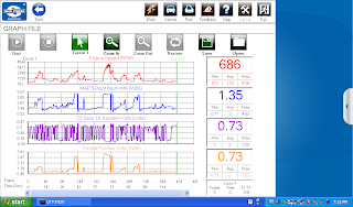
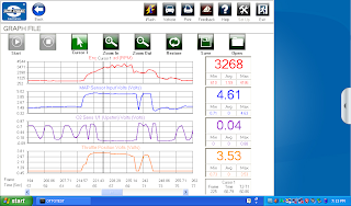
I am looking at Engine RPM, MAP, Upstream O2 Sensor, and Throttle Position. I head out and the vehicle runs pretty good out on the road. I really lean into the throttle and this vehicle noses over, bucks, and shakes. Let off the throttle and it recovers. In fact if you just drove it around normally you would think it ran great. I get back to the shop and concentrate on the part of my road test at heavy throttle.
I blew up the portion of the graph and added a cursor. O2 sensor voltage plummets on heavy throttle. If you asked me to diagnose this car without scan data I would have said this thing had a bad crankshaft sensor or bent flywheel. I would have never suspected fuel. But, this is why we do the testing.
I knew we were on to something when I hooked up my fuel pressure gauge and the engine stalled. Restarted the vehicle and have 50psi engine running at an idle. This returnless fuel system should have 49psi all the time idle, cruise, wide open throttle. So far so good as far as pressure.
I flash the throttle and the fuel pressure drops like a rock. Here I caught it at15 psi. Hardly what we should see. I open up my volume knob on my gauge and the fuel just dribbles out and the engine stalls. When these returnless systems have this condition they tend to aerate the fuel which can also setup misfire codes as well. The aerated fuel makes it to the injectors and causes a misfire until the air is purged with good fuel flow.
A check with a low amp probe reveals a pretty decent pattern and decent amp flow at 5 amps. At this point I know I do not have a connection issue or an available voltage issue. I suspect an issue with the in tank fuel filter or strainer. I tell the shop to drop the tank and with this mileage replace the fuel pump module assembly which includes pump, filter, and attaching parts. All is well after the pump module replacement and runs well under heavy acceleration.
Our final Jeep is a 2006 Wrangler 4.0 liter with 59,564 miles on it. It was in this shop for some type of crankshaft sensor code. The customer supplied the crankshaft sensor and the shop installed it and we still had a code. I hook up my DRB3 scantool and retrieve a code P0016 that is current. Lets look at the code set criteria for a P0016.
Remember, to click on images so you can read them. Well not very particular in their code set criteria. How much out of phase before the code sets? There is a pid called Cam/Crank Difference. It has a value in degrees. mine is sitting at 14.6 degrees. Experience has shown me anything 8 degrees and better is an issue. Obviously, we would like it as close to zero as possible. Over the years timing chain/belt and gear wear cause this to wander. Service information gives you no adjustment procedure other than the cam sensor housing initial installation. Did someone do some motor work on this Jeep? A call to the customer confirms that there was no motor work done. The call also helps me with my path of diagnostics. When I ask the customer if there are any drivability issues with this vehicle he tells me "Oh yeah it breaks up over like 3500 rpm's." Thorough interrogation of the customer and their problem is essential in this business. It is amazing what you can find out through a few short moments with the customer asking the right questions. Onward. Now we know it also has a drivability issue as well. My next step is to scope the cam and crank sensors in dual trace to check their actual relationship.
I use two markers in looking at Chrysler NGC (New Generation Controller) 6 cylinder cam and crank relationship patterns. The NGC patterns are much different than the old SBEC (Single Board Engine Controller) or the JTEC (Jeep Truck Engine Controller) patterns. You have to know your enemy thoroughly. Thankfully every NGC 4 cylinder looks the same, every 6 cylinder looks the same, etc.
These are my two markers that I use. First up is the single cam pulse that occurs after the double pulse. The rising edge of this pulse should occur right after the second pulse after the high (5 volts) "signature" notch of the crankshaft sensor signal. In the above example it is occuring somewhere between the third and fourth pulse after the signature notch. The other marker I use is the triple pulse of the camshaft. I normally see the the middle pulse on the pulse of three ocurring somewhat close to the middle (actually a bit to the right) of the low (ground) "signature" pulse. Here you can see it is ocurring at the first pulse after the low "signature" pulse. So we know we are off, the scan data was telling us as well. The scope confirms it. So, now what? I have seen plenty of cam/crank relationship errors caused by cheap aftermarket crankshaft or camshaft sensors, bad flywheels, timing belt/chain stretch, etc. Normally, when I see a broken flywheel the patterns are shifted in the opposite direction. I look down at the camshaft sensor and it's housing. Service information says when the cam sensor housing is installed correctly the cam sensor will be at the 4 o'clock position looking over the right front fender. Hmm. mine looks a bit off. Mine looks more like 5 o'clock. Now there is no factory adjustment procedure to adjust. Only to install. Let's go for it!
Not bad at 3 degrees. I can live with that. Now what about our scope pattern?
Wow! Spot on! Look at the markers I discussed earlier. I clear the code and relearn the cam/crank values with the scantool. Which should be done if there is any sensor replacement or adjustment. I start the vehicle repeatedly to make sure we have no more MIL lamp. Recheck values and road test. I am happy to report the Jeep pulled hard all the way up to 6000 rpm. So now the question is why was the cam/crank relationship so far off? Well, I believe there was "Hotrod Harry" mentality at play here. The owner of the Jeep and his friends like to "play" with cars. I believe maybe one of them thought by altering the position of the cam sensor housing he was gaining horsepower or something like that. The bolt at the holdown looked like there was someone there prior. The other explanation is that it is not uncommon for the gear at the bottom of the cam sensor housing to wear a bit. I advise the shop owner of my thoughts on why cam/crank relationship was out and marked with a paint pen on the cam sensor housing and block two witness marks to alert me to anymore "reengineering".


No comments:
Post a Comment