Sunday, February 8, 2015

Communication Breakdown


This 2008 Jeep Grand Cherokee with 68,592 miles on it has an issue. The shop owner called me saying that dash gauges, turn signals, power locks, and radio were all inoperative. Furthermore, the dash had every warning lamp illuminated. The vehicle started and ran quite well. I arrived at the shop and sure enough the complaints were verified. I have seen ignition switch issues cause this same set of circumstances before. I checked voltages at a couple of places and quickly ruled that out. It was time to dig deeper.


I hooked up my WiTech system and quickly saw that one whole communication data buss was inactive. The codes I pulled from the FCMCGW (Front Control Module Central Gateway) confirmed what I saw on the topology screen. I needed to check actual voltages on the CAN B buss.


Here is a little network topology layout for this Jeep. Let's review operation. We will start at the FCMCGW. This is the central hub or gateway for both the CAN-C buss and the CAN-B buss. It also translates to a Diagnostic CAN-C buss to the Data Link Connector. Some earlier diagrams will show this as CAN-D for CAN Diagnostic. CAN-C modules are items that need high speed data transmissions for operation such as PCM, TCM, ORC (Airbag Module), etc. This data buss typically is not fault tolerant. In other words if we have a short to power, a short to ground, an open on one wire the buss will be compromised and will not function properly. CAN-B buss has slower speed data transmission and such has "non-essential" modules on its wiring. These include Drivers Door Module, Sunroof, Parking Aid, etc. This buss is fault tolerant. If one wire was open or shorted the modules would continue to operate. Fault codes would be set however. Both CAN-C and CAN-B are two wire twisted lead buss systems. Both buss systems "mix" at FCMCGW. I need to check CAN-B buss voltages. Hmmm, where to check.


My favorite spot and easiest on this platform is under the passenger front seat at the Heated Seat Module. I backprobe with my scope on both CAN-B buss wires at the HSM. I have absolutely no activity. I spared you the scopeshot. I also verified proper power and ground at the HSM. This can play an important factor as well into buss communication. Now, I am left with do I have a wiring issue or a module fault. I go back to my WiTech.


I go into the Loss of Comm Test. This shows all the modules that should be there and if they are reporting. As you can see all the CAN-C modules are reporting as well as the FCMCGW. All of the CAN-B modules are not reporting and more importantly they all have the same number of no responses. I leave my scope leads in at the HSM and disconnect the connector and cycle the key. Still no activity on the buss. I always try the easiest action first. So I know that my HSM is not my issue. I have a communication breakdown. There is a reason I named this post communication breakdown. It is one of my favorite Led Zeppelin songs. When I find myself getting scattered I can always count on the music of Led Zeppelin to get my on track again. So, I go back to my truck get some Zeppelin on and look at a wiring diagram for the CAN-B buss system.


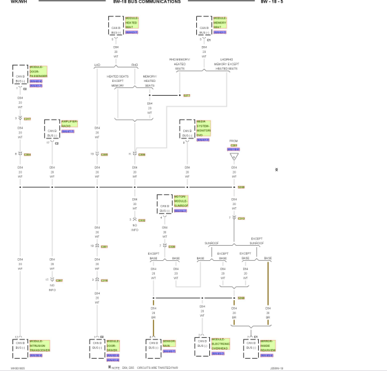
Here is one leg of CAN-B. Something is corrupting the CAN-B buss. That is a lot of modules to disconnect one at a time or wiring to check. I close my eyes and let the voice of Robert Plant carry me away to even me out. What do I always say and preach? Break it down or divide and conquer. I look at the wiring diagram looking for my best course of action. What will give me the best results.


As Jimmy Page belts out yet another one of his signature flawless riffs it comes to me. This C313 will give me possibly four modules if I disconnect it. Ok, now lets look where it is. Service information says it is located left rear of vehicle behind an interior panel. Great. One thing the liftgate is inoperative. Yes, I could pop that panel off and manually unlock it but that is more work. I crawl over the seats and was able to get to the left rear interior panel that hides C313.


I pry it back a bit to uncover C313. I disconnect it and the horn starts going off. Bingo! I jump back out. Hit the remote to shut off the blaring horn and cycle the key.


I am now able to open the liftgate. Here is that panel as viewed from the open liftgate area. My scope reading at the HSM show activity. I go back to the Loss of Comm Test.


Here it is after disconnecting C313. Now, the only non reporting modules are the Sunroof and the EOM (Overhead Console). All functions are restored save the Sunroof and EOM. I inform the shop owner that further diagnostics would require dropping the headliner to disconnect said modules and inspect wiring to the modules. I am leaning heavy to a bad Sunroof module. The shop owner then tells me that last summer this vehicle had issues with sunroof drains clogging. At this point the shop owner also advises me to leave C313 disconnected until he asks the customer if they want to go further. Apparently, the customer just called and their other vehicle broke down that morning and they are without a vehicle and need a vehicle desperately. I pull out of the shop with the sounds of Led Zeppelin pouring through my speakers. Hey Hey What Can I Do.

Sunday, February 1, 2015

Mailbag

I get quite a few private emails asking for advice or problems concerning a vehicle. Rather than answering them privately I will answer them online so we can all benefit. I will display the email in full as it was sent but I will not disclose the senders email address. Just in case they want to be anonymous. Please realize I get email from all over the world so sometimes spelling and sentence structure may not be perfect. Cut them some slack.  Here are a few. My answer will be in blue writing.


Hi i am a technician that reads your blog with great anticipation , i recently had a 05 max semuler to your 06 maxima you covered in your 2015 January blog came into the shop running and then would not start for nothing with the same symptoms .  Customer would not go no further with the reapers or diagnostics but i feel pretty sure it was the seem problem . You make it look so easy  ,  if you had to choose between diagnostic equipment , training , information what would you chose why and in what order and thank you so very much looking forward to the next one , just wondering have you considered videos sometimes and thanks again you are the man .

Thank you for reading. I really enjoy getting feedback from the people who read it. Believe me it is not easy. You see after it has been processed and written up. Plus, after the repair has been made it always looks easy and logical. I get my butt kicked just like every other tech. I always look at it as a learning experience. Even though when I am in the heat of the moment I don't think that way. 

On to your question about choices. I would not be able to choose between the three. They intertwine and are dependent on each other. You need diagnostic equipment. But, you also need training to use the equipment to it's full potential. You definitely need accurate current information to repair vehicles today. There is so much that you can't memorize information. I think a blend of the three along with dedication by the technician equals a successful career. You have to be willing to put in the time to excel in this industry. You have to ask "Why did that happen?" instead of "I don't care".

I have considered videos. Anyone that knows me will tell you I am better in real life. I am a very animated and demonstrative person. Maybe, I will have to start my video career. As far as me being the man. Thank you. But, I am just one of many dedicated, intelligent, and caring technicians in this industry. There are many "Men" and some "Women" as well. 


Am an automobile technician. I have a 2000 Pathfinder that won't start. There's spark on the plugs and there's good pressure on the fuel pump. I scanned it and got the P1320 code. Pls what do I do?   


Well this can go many ways here. Let's start with the P1320 code. The P1320 in it's self usually doesn't cause a no start. Now let' examine your testing. You say you have spark. How are we measuring that? Are you using a scope? Screwdriver? I would recommend what I call my $14.00 scope. This is an adjustable spark tester that you unscrew to create an air gap. Not a bulb type tester. They are on any tool truck. Get one and unscrew it out to 30KV which is approximately 3/4 of an inch. Now do we have bright white consistent spark while cranking? Then we have to talk about whether we are getting spark at the proper time. That can get a little involved. Many methods from simple to hi tech.

Good pressure on the pump. What was the pressure?  Did we use a gauge? Or did we use the calculation of how far the fuel shot out in feet to pressure calculation? I am kidding on that last one. Where did we put the gauge? In place of the fuel filter, inline or "deadheaded" on the end of the pressure line. This placement will make a big difference. But, hey lets make it simple and fast. If we spray some good quality carburetor spray in the throttle body and crank it over does it kick? Want to start? Or nothing? Are the plugs coming out wet or dry?  

Was there any recent work done to the vehicle. When was the last time the vehicle started? Is the fuel stale? Injectors glazed over from rotten fuel? What kind of tooling do we have at our disposal? These are all factors to consider. Start with spark quality and then see if it wants to kick on carburetor spray. Keep us posted and I am sure we can get your Pathfinder rolling again or give it a proper burial. 


Sunday, January 18, 2015

Work smarter not harder


I get a call from a shop owner. He explains he had this 2002 Mitsubishi Montero Sport 3.0 liter towed in for a no start. They found a broken timing belt. He explained to the customer that the timing belt broke and there may be valve damage from the broken timing belt. Some engines are interference and others are non interference. Another factor to consider here is the vehicle is being towed in as a no start. The shop has no way of knowing how the vehicle ran prior to the timing belt breaking. The customer gives the okay for the timing belt replacement. The timing belt is replaced and the vehicle starts but runs poor. It has a very rough idle and a misfire. Now, the shop owner is wondering is the timing belt installed right? Are there further issues? He calls me and wants me to check it out. I arrive at the shop and the vehicle starts and definitely runs poor with a misfire. Now, I need to give you some setup on my next step.


Here is my high amp probe. It has a 600 amp capacity. It is different from my low amp probe in its capacity and scaling. Basically, with this probe 1mv equal 1 amp. It's large jaw capacity is a necessity for the next test I want to perform. I want to check compression on this vehicle. I don't want to spend all day taking spark plugs out and on this vehicle removing the upper intake to gain access to half the spark plugs. We are going to do a relative compression test. It is one of my favorite tests. Easy to do and packed with information. This test will measure the amount of electrical current needed to turn the motor over as it relative to each cylinder. What we are looking for is uniformity between cylinders. We are also looking for a proper cranking amperage as well.


To perform this test I disable fuel accordingly. You want no fuel flowing into the cylinders and washing them down giving you inaccurate testing.  Then I setup my scope with amp probe around a battery cable with the arrow on the clamp in direction of current flow. Then we are going to crank the engine over, record, and analyze the results. A couple of key points here. You must have a good battery and starting system. No battery chargers. A jump box is acceptable. A donor battery is sometimes needed if the vehicles battery wont support 20-30 seconds of cranking. Lets give it a crank.

 
Here we have some cranking time on the screen. What we are looking for is uniformity. We are also looking for about 150 cranking amps and about 30-40 amp differential between high and low points. We have about 4000ms of time which is 4 seconds. I see something that stands out.


I zoomed in a bit here and highlighted what I saw. Every sixth pulse is low. The pulses are representative of our six cylinders. We have about 150 amps and approximately 30-40 amps from high to low. Now, we know we have a cylinder that has substantially lower compression due to the low amperage load to "turn" that cylinder. The next cylinder after a low cylinder will usually be a higher amperage load as it "catches up" so to speak. Ok, so we know we have a low cylinder. But, which one?

 
Our next tool is an ignition synch probe. This will go around an ignition wire and will display a pattern when spark is flowing through the ignition wire. This pattern will not be detailed like a true blue ignition probe but all we are looking for is a reference here.


I place the probe around number one ignition wire. Crank the engine over again. The shop left the timing belt covers off here.


Now, we have some reference to work with. The large green spikes are cylinder number one firing. Most vehicles will crank somewhere near TDC so the spark spike should split the relative compression spike right in the middle. That looks good here. Now we can find out our low cylinders identity. Let's mark it up.

 First, we need to identify firing order. I also use this diagram to verify where cylinder number one is. Always consult the service information. If in doubt reference several sources. We need to be sure.


I marked it up with the firing order. Now we can definitely say that cylinder number 3 is not happy. Do we have a hole in the piston, a valve not seating, a broken valvetrain component? Well we really can't say from this. But, we saved about 2 hours of labor. In 15 minutes we are here and the most labor we did was to disable the fuel system. I do a couple of more tests before talking to the shop owner.


 I scope crankshaft and camshaft sensors to see if the timing belt is correctly installed. Typically, if the timing belt was incorrectly installed it wouldn't affect one cylinder it would be multiple cylinders. But, it only takes a minute.


I compare our pattern to the service information and it looks dead on. Please note that service information is different than my scope pattern as far as placement of signals. The service information has the crank sensor pattern on top where as I have it on the bottom. I always put my crankshaft sensor pattern on the bottom and I always use channel 1. It is the OCD coming through.


I look at the ignition pattern on a known good cylinder. In this case it is cylinder number one. We have about a 7.5 KV spike and noticeable cylinder turbulence in the firing line. This cylinder is working. Lets look at cylinder number 3.


Here is our bad cylinder low 3KV spike, a long firing line, and no turbulence at all. This cylinder is not contributing. It is like its firing the plug in the atmosphere instead of a combustion chamber. I inform the shop owner of the correct timing belt installation and the low number 3 cylinder. I advise him that from here we can do a leakdown test or I can use a pressure transducer in the cylinder coupled with a vacuum waveform to pinpoint the issue. He tells me he will take it from here. Cylinder three is accessible without taking the upper intake off. The whole idea here is to work smarter not harder. The tooling used here is within the reach of most techs.

Tuesday, January 6, 2015

Keep the change


Here we have a 2006 Nissan Maxima with 129,002 miles on it. The vehicle is driven to the shop with a complaint of no instrument gauges, ABS and TRAC lamps on, and the heater panel selection buttons are illuminated even with key off. This happened all of a sudden. The shop called me in to look at the vehicle and diagnose the issue. I begin by confirming customers issues and a visual.


Ok this is with the car running for approximately 10 minutes. Fuel gauge and temperature gauge are inoperative.


Here we have the other side. No tachometer operation and various lamps on for the ABS/TRAC system. This problem is happening right now. My favorite type of issue. Now I can roll up my sleeves and get to work. Nothing worse in my business than an intermittent issue. It eats up a lot of time and they never seem to act up when I am testing. I do plenty of intermittent issues and it takes intelligent testing and patience. Some days I am neither intelligent or patient. Back to our issue. My next step is to hook up the scantool and take a peak at what is happening.


Here, I am using the Nissan Consult 3. A 2006 Nissan Maxima is a Consult 2 vehicle but Consult 3 and Consult 3+ are backwards compatible for diagnostics and sometimes for programming. I do a full scan of all modules for DTC (Diagnostic Trouble Codes). This is first page.


Here is the second set after scrolling down. It seems very apparent that I have CAN (Controller Area Network) issues. The common thread is the U1000 code. The other comes from experience I do not see a Instrument Cluster reporting or as Nissan calls it a Meter. When I see U1000 codes in multiple modules it usually means a module that should be there is not reporting. My next step is to use a very slick feature of this factory tool.


This feature is the CAN DIAG SUPPORT MNTR. My relationship with the Nissan Consult 3 scantool is a love/hate relationship. Some days I would like to turn my laptop into a Frisbee when using this tool. Other days I can't say enough about it. This is the feature that keeps me using it. I can select a module on the right and then the tool will poll that module and the module will show on the left which modules it is recognizing and communicating with. In this case I am asking the ECM what modules it sees. I see something right away.


Look at the red arrow. Presently the Meter is Unknown. All the other modules are OK or in other words they are present. Lets check another module.


Here we are asking the BCM. Same thing Meter is Unknown. See the pattern. I hit the Result box in upper right corner.


Here you will get CAN H and CAN L voltages as well as system voltages at the DLC. I usually sneak a look at this but always back it up with my labscope. In this case I don't need my scope. I know where to go but lets get some theory and wiring background.


Here is a partial wiring diagram of the system. It is enough for some theory and demonstration. You can see the combination meter a.k.a Instrument Cluster a.k.a Meter gets data from a module called an Unified Meter and AC AMP. Nissan loves to integrate modules for multiple tasks. It is one of things that make them very challenging. Let's get some theory behind the wiring.

  
From the factory service information. Pretty much what we see on the wiring diagram. So this module controls air conditioning control and processes signals from the CAN lines to send to the Instrument Cluster/Meter. I think we found a prime suspect. Let's get back to the car.


I have been here before. I know where this Unified Meter and AC Amp resides. Here is a shot of the ac panel, every light on. One word of caution here. See the aftermarket radio lurking underneath. I have seen incorrect aftermarket radio installations cause these issues as well. The customer confirmed that this radio has been in here well prior to this issue. See that white module above the ac panel? That is our culprit.


Some more screws and out it comes. Like I said been here before. As I am removing the module I hear rattling from the module as I turn it over.


Finally free at last and I can shake it and it sounds like a baby rattle. A quick sniff of the module reveals the smell of burnt electronics. See that small slit on the right side of the module? It is the perfect size for a penny, a dime, or a nickel. I always challenge myself as to how much change I am going to find inside and usually have a bet with the shop owner. I bet 6 cents. Incidentally, new modules come with a piece of tape over that slit.


I lost 11 cents is the winner. This is a very common issue. This 11 cents just cost this customer much, much more. I have seen this cause no starts if it shorts the CAN line down.


So common that Nissan issued a TSB about this issue. I tell the shop owner my findings and guide him through the TSB. A few days later a new module is installed and the Maxima is back to operating normally.


Here is a shot from another Maxima showing the area how it is stock and not torn apart. Keep that change off that ledge.

Sunday, September 21, 2014

Safe and Sound


This 2014 Chevrolet Cruze with 3,134 miles was in a recent collision event. The body shop did a great job of putting humpty dumpty back together again. Part of the repair was the replacement of the SDM (Sensing and Diagnostic Module) for the airbags as well as several other airbag related items. On many late model GM products the SDM comes blank and needs to be programmed and a setup procedure completed before the airbag lamp goes out and the vehicle can be returned to the customer. This is where I come in. Now I always tell the body shop on GM products that they have to have all the bad components replaced and a brand new GM SDM needs to be installed. The reason for all the faulty component replacement is because the SDM will not finish the setup procedure if there are any
faulty components such as open connections, blown out pre tensioners, etc. The reason for the GM module is simple. There are many outfits that claim that they can rewrite crash data on a SDM and then it can be reused. I personally don't agree with this and have always have had issues when trying to setup these modules. The normal price for a GM SDM is typically not that expensive why waste your time. So lets get the show on the road.


So the first step is to program the SDM. This will program the proper software into the module for this particular vehicle it is VIN driven. I hook up my laptop and use my GM MDI for an interface. I also attached my Midtronics battery maintainer and checked for proper voltage for programming. Using GM SPS I program the new SDM with the proper calibration. The screen above is just confirmation of a successful programming event. There are also valuable instructions in the smaller box. Basically, it says you must now run the Setup SDM application successfully for the module programming to be complete. I run the Setup SDM application which is a two part procedure. The first part marries the new SDM to the vehicles BCM. This procedure is called Setup Primary Key in BCM which it completed successfully. The next part is to Enable Deployment Loops. This vehicle failed to run this application successfully. I knew it wasn't going to be successful because the airbag lamp after programming the SDM was on solid. It should be flashing. Ok, the body shop must have missed something. This happens all the time when a part doesn't get installed or a connector is not attached properly.


This vehicle is a Global Architecture vehicle so a Tech2 will have limited to no data. Instead the factory tool here is GDS2. It is a software you lease from GM TIS. I run it though my GM MDI as this is the true blue factory way. There are other interfaces that work quite well with GDS2 as well. GDS2 is not as intuitive as the TECH2 and does take some getting used to. Lets check for some codes in the airbag system.


Here is a few screens in. The modules are listed on the left. I choose the airbag module.


Here is the trouble code screen. It tells me the trouble code and subcode, description, and status. As you can see we have three current trouble codes. The configuration code is due to the SDM not completing the Setup procedure. Our issues are with the two other codes for passenger side seatbelt pretensioners. Lets get some data.


I head into the Module menu and choose Data Display.


A wealth of information can be found in data now. Early GM systems had almost no useable scan data. Late model vehicles it is information overload. I choose Deployment Loop 1-14 Data. I am looking for something to smack me in the face.


There it is Loops 6 and 8 are different than the rest. The 25.50 ohms reading I see is typical of late model GM for a completely open circuit. Look at the other pids all typically between 2 to 3 ohms which is industry standard. Lets look at the items in question physically.


This is the drivers side seat belt seat pretensioner. This is how it should look-this is normal and our scan data supports this. Lets have a look at the passenger side.


A little different, right? When the vehicle was in the collision the SDM "blew" the pretensioner here and the belt sucked in to lock the occupant into the seat for safety. Ok, now I tell the shop owner we need more parts. I explain the issue and the fact that when he has all the parts correct the airbag lamp will flash. At that point I can come back and finish the Setup Procedure.


A couple of hours later I get a call from the shop. Parts are installed and airbag lamp is flashing. These are the old parts. One part is the aforementioned seatbelt pretensioner and the other is the B pillar belt assembly which also had a code for an open pretensioner. Remember, the codes.


Here is the after shot. Now, lets recheck that data.


Now, that's better. Time to run the Setup Procedure.


I choose the Configure New Module application in GDS2. It runs and completes. The airbag lamp goes out. Lets check for codes to be sure.


Success. I turn the key off and restart the vehicle making sure the airbag lamp goes through its normal cycle. I also check the PPS (Passenger Presence System) for proper operation. A recheck for codes and inform the shop owner we are good to deliver the vehicle.