Sunday, November 25, 2012

2001 Cadillac Seville SLS


There she is. One 2001 Cadillac Seville SLS with 103,361 miles on it. Pretty clean car. Unfortunately, it does not start, nor crank, nor does the host of electronic gadgetry on this car work. The owner says sometimes he can disconnect the battery and reconnect and vehicle it will start and perform well. Notice the battery charger in the picture. Usually, a clear indication to me that the battery in the car is a paperweight. I see a ton of bad batteries. People will have expensive stereo systems, fancy alarms, and they have a bad battery. They don't mind jumping the car 5 times a week. That spells disaster to electronics. Between, voltage spikes and the eventual backwards jump start it gets ugly fast. Let's get the show on the road with this car.
I hook my Tech2 to see what modules are reporting. I choose Class 2 DTC Check to see what is going on quickly.

This is what I get. Now, this could go many ways here. These vehicles have lots of issues. Bad ignition switches, water leaks soaking modules and causing communication issues. On this model I know that they typically will have windshield and/or passenger door leaks and the SRS (Airbag) module under the passenger seat gets soaked and causes issues. A quick feel under the seat and it feels pretty dry. I then break out the scope and check pin #2 at the DLC and get a constant 12v. The Class 2 communication line is shorted to power. So many things can cause this-bad modules, shorted harnesses, poor grounds. Lets look at the Class 2 line.
Here is part 1.....

Here is part 2. Lots of modules here which is to be expected on a Cadillac. These modules are arranged in a Loop pattern. GM has 3 different ways to arrange Class 2. Loop is what you see here where communication lines go in and out of every module. Star arrangement where each module generally has one communication wire going to it and there is usually a splice pack where you can take one module off at a time. Finally there is Star/Loop which combines the two. Loop is great for redundancy but can be a little more intensive to diagnose. I like to start with easy. I visually check grounds and harnesses for rubbing or damage. They look pretty good. Next, I start disconnecting modules, cycle key and then look at my scope on Class 2 for activity. I disconnect ABS no luck. Every other module is buried except one-the PCM.
I unearth it and disconnect both connectors.

This is what I have at pin #2 at the DLC now. Perfect Class 2 waveform. Let's recheck the modules with the Tech2.

Nice! I now have modules reporting. The only module not reporting is the PCM. Obviously, it is hanging in the breeze. A quick check of powers, grounds, and 5vref at the PCM reveals no other issues. This PCM is the cause of the Class 2 being shorted to power. Remember, the battery charger, etc. I inform the shop owner of my findings and give him options so he can discuss with this customer. He calls me the next day and tells me money is tight with the customer. He wants to go with a used PCM and still does not want to change the battery. I do not mind setting up used modules as long as it will not cause issues. Be careful. Sometimes replacement of used modules will cause issues. Ask one shop I got called in when they changed a BCM (Body Control Module) on a Caravan to fix a rear wiper issue. Well after the used BCM went in the vehicle got infected with VTSS (Anti theft) and the mileage almost doubled with no going back. Try explaining that to the customer. Be careful! All my customers know to call me first and ask me about used module beforehand. It is something I preach. Ok, so we are going to be putting a used PCM in this Cadillac. New, reman, or used it will have to be setup with proper VIN and calibration. As well as the theft system relearned.
Used PCM installed. Still have great communication. Next....
I hook up my Midtronics battery maintainer to the battery. Not because this vehicle has a bad battery. I will not reflash, program, etc without it. It is a ripple free battery maintainer that holds voltage steady at 13.4v. It is endorsed by GM and has been the industry mainstay for some time. I know guys that flash with jumpacks or battery chargers. I do not have that kind of luck. There is a lot of data being transferred and I want to make sure I have done everything for a successful flash event. A quick check with my DVOM at the battery tells me we have stable proper voltage. Next, I hook up the Tech2 and request info from the used PCM. It will have the VIN and calibrations from whatever vehicle it came out of. I will be overwriting that with proper VIN and calibrations for this vehicle.
I then hook up my Tech2 to my TIS2000 program, input the proper VIN and choose replace and reprogram PCM. This is what is called remote programming. It is when you are downloading calibrations to the Tech2  from the laptop then disconnecting and using the Tech2 stand alone to update programming. Sometimes I use this method other times I use pass thru. I avoid flashing/reprogramming with a J2534 tool whenever possible. I like factory tooling. Less pitfalls and suprises.

There are the correct calibrations. I upload to the Tech 2 and go back to the car.

Here is where it gets a little dicey. These Cadillacs along with certain Corvette models (check your service information) really should be programmed by themselves. Apparently, with so many modules on the communication line if one of them "talked" while a programming event was going on it could corrupt the programming. So GM recommends to reprogram these PCM's with a special stand alone harness that isolates the PCM. Others, I know have made jumper harnesses of their own to work around this. I had some good information that if I pulled the I/P fuse in the underhood fusebox that the chatty modules involved would go to sleep and I could program this PCM. So I did.

Here I rechecked. Sure enough my chatty modules are no longer reporting and the PCM is there. A quick recheck of proper voltage and connections. Lets program!

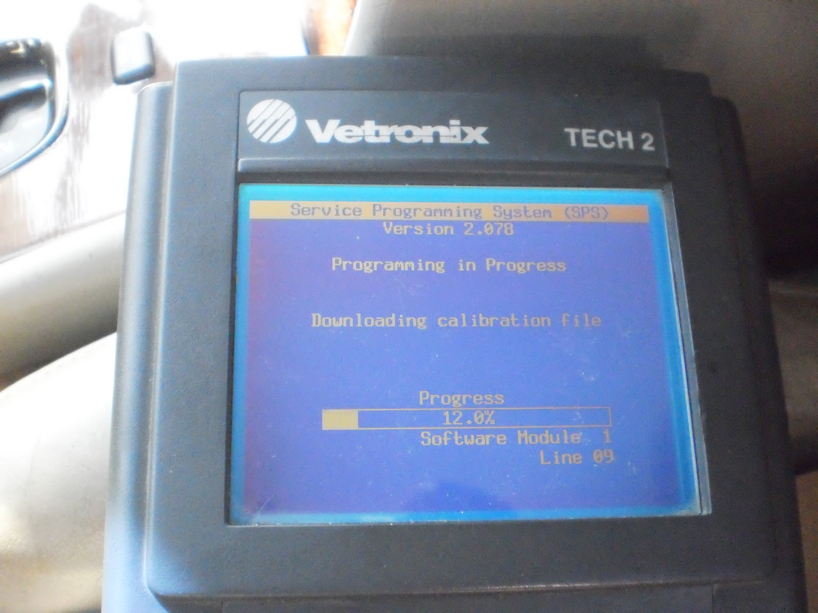
Here we go.

A couple of minutes later. Lets recheck for proper calibrations.

Bingo. Vehicle still is not going to start. We need to relearn theft.
Here we have a choice to relearn theft. GM typically gives you two choices. One is a long way typically 30 minutes which involves turning key on and waiting, etc. The second way is a program that will run that speeds things up. That is what I use. Again, we request info from vehicle using the Tech2. This time VIN is correct.
I choose theft relearn and upload it to my Tech2.

This is a lot faster. After completion the vehicle starts and runs properly. I clear all codes and make sure to perform any after reprogramming procedures such as oil life reset, crankshaft variation relearn, etc. The Cadillac rides again. Hopefully, that battery gets changed sooner rather than later. 


Sunday, October 28, 2012

Korean Chaos

Well, it has been a long time since I last posted and I would like to catch up. Thankfully, business has been good and I have had little downtime. Here is a 2004 Kia Optima with a 2.4 liter 4cylinder motor. I see a ton of Hyundai/Kia vehicles in my area. They are very popular. The shops concern is the vehicle seems to run pretty decent with a slight lack of power but once warmed up has a very shaky idle. There no codes. I first look at some fuel trims which seem to be acceptable. I road test the vehicle and no doubt it is slightly underpowered and indeed has a shaky idle. I decide to look at engine vacuum to start with because the vehicle feels like the EGR valve is stuck on at an idle.
As you can see 14" of vacuum at an idle. I normally see these vehicles produce 19" of vacuum on a good running vehicle. The low vacuum is a clue. The next thing I do is feel the EGR valve with the vehicle running. It feels pretty cool the touch. Now, this is not an absolute foolproof diagnostic test. However, typically if an EGR valve is flowing some exhaust gases it will be warm to hot to the touch at an idle. Warning, do yourself a favor hit the EGR with a non contact laser thermometer first before putting your hand on it. Ok, EGR not flowing at an idle, what is next?

I like to scope things. I feel it gives me the best bang for the buck. In my business remember I need to be fast and efficient. I want to look at crankshaft sensor to camshaft sensor patterns and how they correalate to each other. If you notice the cam sensor is driven off the exhaust camshaft of this car.
Here is the CKP sensor pattern in yellow on channel 1 and the CMP sensor pattern on channel 2 in green. Call it my OCD or whatever I typically always use channel 1 for CKP sensors, it keeps captures consistent. Ok, is this a good pattern? This is where data acquisition comes into play. So I pull up a known good waveform from my library.

Here again CKP is channel 1 in yellow and CMP is channel 2 in green. What I can see immediately is that the Cam sensor pattern either intersects the Crank sensor pattern halfway or straddles it midway. Lets revisit the vehicles waveform at a different timebase.
It is shifted no doubt. Be careful using this method. The pitfall is that the Cam sensor is only on one camshaft. So we could have a situation where one camshaft that drives a sensor is in time and the other that has no sensor is off. When presented with that situation I use running compression with a pressure transducer and look at exhaust and intake valve opening events. Here, I didn't have to. I advised the shop to check timing belt alignment. Sure enough they called me back later that day after resetting the timing belt. The vehicle performed and idled well.

I recently was at a shop that just did a timing belt replacement on a 2004 Hyundai XG350 3.5 liter v6 with 75,136 miles as part of routine maintenance. The vehicle ran well into the bay. Unfortunately, it ran quite poorly after the service. It was setting misfire codes and had a terrible lack of power and a rough idle. These cars normally idle like glass and perform quite well.
The tech that did this job was sickened. He is a very thorough tech and I have been there a couple of times in my life where the vehicle ran worse after I serviced it. It is a bad feeling. I really felt for him. I went over the timing belt procedure with the tech and on the car several times. I often find that more can be found out asking questions than looking at the car. After some head scratching the tech said something that stuck with me. He said he had a hard time seperating the crank pulley from the crank sprocket. With this I broke out the scope and decided to check CKP/CMP correalation. I had a hunch.
Here again CKP in yellow and CMP in green. I didn't have a known good pattern handy. But, I felt very confident that it would follow suit like the Kia previously. Here, is another shot.
Cursor 1 is where the rising edge of the CMP sensor is and cursor 2 is where it should be. I know what happened. I tell the tech to get the timing belt off and remove the crank sprocket and CKP interruptor ring behind the crank sprocket.

Here is the interruptor. Those blades pass through the CKP sensor causing the square wave pattern. If you notice there are two dimples on the ring that should not be there.
Here is the backside of the crank sprocket. The two protrusion tabs that should go into the holes on the CKP interruptor ring are worn off.


Here is how it fits together. What happened here is when the tech was seperating the crank pulley from the sprocket it pulled the crank sprocket forward and disengaged the CKP interruptor ring from the crank sprocket. When the tech reinstalled everything it moved and therefore corrupted CKP/CMP timing. This caused the vehicle to run like the timing was retarded drastically. This was very easy to do. Hyundai does not extend the crankshaft woodruff key all the way in and relies on these two small tabs that are easily broken to index everything. One new crank sprocket and interruptor ring and away it went.       


Tuesday, June 5, 2012

2001 Nissan Pathfinder


Here is one 2001 Nissan Pathfinder with 141,893 miles on it that is due for state inspection. The dilemma is the vehicle has the dreaded P1320 code for primary ignition. This is a very common code on Nissan vehicles with COP (coil on plug) ignition. There are three items that I see that will cause this code. One is bad COP units (more on this later), wrong spark plugs, and someone has tied the rpm input for a remote start into one of the COP units. The shop owner asked me to look at this because the customer cannot go for 6 new COP units. He needs a definitive answer on how many COP units are bad and if other issues are at hand. The code set criteria for this code is a little misleading. Basically, it says that there is a missing primary signal. So, this vehicle should be missing, right? Well, this vehicle runs well with no apparent misfires. Time to pull a wiring diagram.


Here is two out of three pages of wiring for the ignition system. It shows that the power for the COP units comes from one contact of the ECM relay. I am only showing three of the six COP units. Those of you that know me and follow the blog know where I am going next. What is going to show me all six COP units in great detail.


Out comes the low amp probe. I make jumpers for both contacts of the ECM relay and I am going to trigger off of #1 COP control circuit.


You don't have to be a scope jockey to see that two amperage patterns are different from the rest. The yellow trace is the coil amperage and the green is the #1 trigger. Forgive my forgetting to zero my probe. Let's add the firing order which is 1-2-3-4-5-6.


As you can see cylinder #1 is lower than the rest and cylinder #4 is higher. These are our two odd men out. Even the pattern at this timebase is not the same as the other four COP units. A good healthy COP unit on this application is typically 6-8 amps. Number 1 is at 4 amps and number 4 is at 9 amps plus. Lets look at these two and a healthy one closer at a better timebase.


Here is number one. Looks to me that there is an issue with this COP unit that is also affecting the trigger. More evidence to condemn the COP unit. Let's look at number four.


A couple things become apparent here. The amperage is high and the ramp is rather straight. Not, what I typically see. Let's look at a good cylinder.

Now, that is a typical Nissan COP waveform. Notice the ramp pattern and amperage. Again, forgive me for not zeroing my probe.


So here we are twenty minutes later and we have a definitive answer for the shop owner. I advised him that cylinders #1 and #4 COP units are the reason for the P1320. I also advise him to check the plugs while he is there. At this point I also tell him do not be suprised if these COP units at #1 and #4 have been changed and are aftermarket units. Sure enough the shop owner calls me the next day and tells me both units were recently changed with aftermarket units. He installed OE units, checked the plugs for proper brand and gap, and test drove the car. He was able to run and satisfy all the monitors for inspection and both he and vehicle owner were very happy. The MIL was out and a sticker was issued. At this point here goes my rant. The aftermarket in it's ongoing quest to provide "cheap" parts has shot itself in the foot. I see this time and time again. Quality doesn't cost it pays. The extra coin for an OE part is money well spent. Here is a prime example.  
 

Sunday, April 22, 2012

A quick update

Sorry, I haven't posted in about a month. Fortunately, I have been really busy. Business has been good and I also have been doing some training at a couple of shops. I have been picking up quite a few new shops as well. I am fortunate enough to have networked with some really good people both in and out of the industry. You can never have too many good people supporting you. The best form of advertising in this business is definitely word of mouth. This is why I give free advice. Many times I will get a shop call me and ask me for an opinion or information. I may not get a job from that shop right away. But, usually I get something from them eventually. They remember I was helpful and knowledgeable and tell other shops.
I should have some more case studies posted soon. I have some more catalytic converter codes, misfires using the low amp probe, some GM electronic throttle control, some reprogramming, an arsenal update, and a one year Ottotest evaluation. Stay tuned. Of course, anything you want to see-email me. 

Sunday, March 18, 2012

2002 Ford F-150

Here we have a 2002 Ford F-150 truck with a 5.4 liter engine and 121,306 miles on the odometer. The customers complaint is an intermittent extended crank especially first start. There is no history on the truck so I do not know if it has well taken care of or not. On a hunch I decided to hook up a fuel pressure gauge and crank the engine over.
This is what greets me. No fuel pressure. I quickly check for spark, injector pulse, and scantool communication. I have everything except for fuel pressure. Now it is time to figure out why. I do not want to disturb anything like connections or relays. So, I head for the inertia switch in the right side kick panel. With that exposed I can use my low amp probe to check the health of the fuel pump circuit and the fuel pump itself.
So, with everything hooked up I crank the engine over and take a snapshot of the scope pattern. The advantages of the low amp probe are many. I like it because it is quick and non-intrusive. Lets look at that pattern.

I get a non modulating 18 amp pattern. This is typical of a fuel pump that is locked up. High amperage with no humps. One thing I can take from this pattern is the circuit is in good shape or else we wouldn't be able to support almost 18 amps of current. Now, there is a caveat here. Be sure to inspect the wiring around the top of the tank and framerail before fingering the pump. So what can we do to also confirm our findings?

We go low tech! A quick wrap on the tank with a rubber mallet is usually enough to vibrate the pump enough to unlock. So I smack and retry. Here is the scopeshot.

Now that is ugly! A couple of more whacks and I get this.
The truck roars to life and this fuel pump sounds like a jet engine. Lets check our running pattern.

Amperage is a bit high at 8 amps peak. I usually see 6 amps or so. The pattern is terrible. This pump has seen better days for sure. I wouldn't be taking this truck too far. I report my findings to the shop owner. He calls the customer and explains the issue and gives an estimate. Customer refuses the job. Oh well, I hope he is handy with a rubber mallet. Here is an example of a good fuel pump pattern for comparison.


 The low amp probe saved me so much time here. It is a great tool to utilize. It tells me more about a circuit and component than any other tool in my opinion. I often see low amp probes in the shops I visit. I always ask if they are using it. I usually get-"Nah" as my answer. Techs break out your amp probes and use them.  

Friday, March 9, 2012

Connections

In my travels I do a fair amount of straight up electrical work. I see my share of shorts, drains, and inoperative components at shops. I have always liked electrical work and it something for the most part shops tend to shy away from. Usually, tracing a short or getting into a battery drain is not as profitable as a brake job and can take up a lot of the techs/shops time. In todays vehicles there are literally hundereds of connections strewn throughout the vehicle. I wanted to share with you a couple I have encountered recently with a common theme-bad connections.
First up is a 2007 Cadillac Escalade EXT with climate control seat issues. This vehicle has both heated and cooled front seating with a mini blower motor for each seat. This is all controlled by the CCSM (Climate Control Seating Module) under the passenger front seat. I first became involved with this when the shop called asking me if I could program a new CCSM they were going to install in this vehicle for the problem of no operation of climate controlled seating. The dealer told the shop it needed to be programmed. Most GM modules do need to be programmed. A quick check of service information revealed this did not need programming it was "plug and play". I advised the shop of this and they installed the new CCSM and still had no climate control seat operation. That is where I came in. I first verified proper inputs to the CCSM with my Tech2 and also backprobed powers and grounds at the CCSM. All were good. Why wasn't it working?
Let's disconnect the connector and check for pin deformation, etc.
Well here we go. The main power feed terminal for the CCSM is smoked. I checked resistances of the seat heaters and blower motors from the disconnected connector. All were in specifications. I then amp drawed the circuits to check them dynamically and again all were good. A lot of current under the best of circumstances goes through this terminal. Better to be safe than sorry. A call to the dealer revealed they had this pigtail in stock-no suprise there, huh? A new pigtail was installed and we can now keep our butt warm in the winter and cool in the summer. How did we ever do without this?

Next up is a 2003 Toyota Sequoia that the battery would go dead overnight intermittently. The customer swears the headlamps turn on by themselves causing this. The shop has already installed a brand new battery and has never seen this phantom headlamp issue. I get called in and for the first couple of minutes of me manipulating switches and harnesses nothing happens. I turn my head and then look back and the headlamps are on and the switch is off and I have the keys in my hand. A second look and actually the DRL (Daytime Running Lamps) are on. DRL operation is controlled by the Body ECU. I hook up my Toyota Techstream scantool and I see no reason the Body ECU should be putting on the DRL lamps. I try to toggle the DRL relay on and off through the bi-directional functions of the scanner and they just stay on. Could the Body ECU be bad. Well, it is easy enough to disconnect. I do so and the lamps stay on. Do I have a stuck DRL relay? I don't think so since the vehicle should not have had the DRL lamps on to begin with key off. Hmm. Whenever I see phantom issues like this I think of two things-resistive shorts caused by moisture intrusion or bad grounds backfeeding. A quick voltage drop of ground circuits reveals excellent grounds. I am going for the resistive short. I start wiggling connections at the inerior fusebox which also serves as a junction box for many circuits including the DRL's and the lamps flicker. I trace the circuit to a particular connector at the fusebox. I cannot get this connector out of the fusebox. I have pliers on it and I do not want to break it off. I pull an adjacent connector at the fusebox and there are signs of moisture. There is green corrosion all over. I tell the shop owner he needs a fusebox. We finally get the connections out-here is the fusebox.

Taken on some water here for sure. A tech in the shop told me that this vehicle sees a decent amount of beach time in the summer months. Maybe, he got caught in the waves one time. Or, perhaps an old windshield leak. Here is another shot.

The moisture migrated into the fusebox and caused circuits internal to have continuity when they should not have. At first the shop owner asked me if we could save this fusebox. Not a chance!

This next one is from a body shop I service. It is a 2001 Ford Windstar with no rear lighting. Front lighting is operative. This vehicle uses a REM (Rear Electronics Module) to control the rear lighting. It is nestled over in the right rear of the vehicle behind a trim panel-see below.
I hook up my scantool to make sure it is communicating and getting proper inputs and to test the outputs. It is communicating and getting proper inputs. When I try to do output tests for the relays that control rear lighting via the REM-I hear nothing. A look at the diagram tells me that the relay command wire goes straight from the REM to the junction box under the left side of the dash. There are no connectors in between! So no divide and conquer mentality can be used here. To make matters worse the interior of this vehicle is fully intact. Usually, when I get a call from a body shop the interior is torn apart which makes it easier for me. This harness goes across the interior of the vehicle. So, I am thinking is a harness chafed on a seat anchor or rotted right in the middle of the truck. The nightmare scenario of taking this Windstar apart is gnawing at me. I know that the connections at the REM look good. I jump out the relay at the junction box and the rear lighting comes to life. So I know there is an issue at the control for the relay. Let's head for the junction box connector on the back that has the control circuit wire.

Well lookey here. I knew something was up when the connector was a bit of a pain to get out. Yes, water intrusion and Yes there should be four terminals on the top row and four terminals on the bottom. See what is missing?

There is the missing pin welded into the female terminal of the connector. This Windstar I believe has a windshield leak that started this ball rolling.

Finally, we have another fine GM vehicle. A 2006 Cadillac Escalade with complaints of no rear wiper and no rear defroster operation. I hooked up my Tech2 expecting to see a LGM (Liftgate Module) and start my diagnostics from there. No LGM showed up. A check of the wiring revealed no LGM on this vehicle and basically was old school from switch to wiper motor. With the rear liftgate open and the shop owner manipulating the rear wiper switch the interior lamps would come on or go out. That was my first clue where to go. Remember, phantom issues either resistive power shorts or bad grounds. I checked the ground at the wiper motor and depending on where the rear wiper switch was it was anywhere from 2.0v to 10.0v back to battery negative using voltage drop. Ok, we know we have a bad ground. The ground itself is behind the right rear interior panel. I really hate pulling panels when I do not have to. Lets check it at the liftgate connector that is easier.
I move this connector and my voltage drop fluctuates. Lets check the connector ends. I smell bad connection.
Here is one side of the connector.

The other side of the connector. Sorry, for the blurry pictures-you get the idea. Again, a substantial amount of current goes through here. Any loose connection, added resistance, etc will cause this. Terminal repair to the connector and this vehicle was back in action.