Here is one 2004 Jeep Grand Cherokee with 88,656 miles on it. The issue here is no passenger side door functions such as power windows or power door locks. The other issue is no RKE (Remote Keyless Entry) functions as well from the key fobs. The drivers side operations work correctly. The Grand Cherokee platform is definitely one of the more popular vehicles I encounter. They have various issues both common and uncommon.
The shop has done some checking before I got there. Various panels have been removed in an effort to narrow down the search. The first thing that catches my eye is the aftermarket alarm module dangling. I am always wary of aftermarket alarms and their installations. I have seen many issues caused by either bad alarms or the installation. Let's have a look at the wiring diagram.
The system utilizes door modules in each door that communicate through a data buss called PCI ( Programmable Controller Interface) buss. It is very much like GM's Class 2 data buss. It is a peer to peer network meaning that any module on the network has the ability to communicate on it's own. Both the DDM ( Drivers door Module) and PDM ( Passenger Door Module) share a common power and ground feed as well. Looking through the service information I also come across this- I underlined the important tidbit of information.
The DDM and PDM each utilize integrated circuitry and information carried on the Programmable Communications Interface (PCI) data bus network along with many hard wired inputs to monitor many sensor and switch inputs throughout the vehicle. The PDM also receives inputs through an integral Radio Frequency (RF) Remote Keyless Entry (RKE) receiver. The DDM and PDM control and integrate many functions and features of the vehicle through both hard wired outputs and messages over the PCI data bus.
We also know that at least our source for power and source for ground is good since we have proper drivers side window and lock operation. So what is next?
This is what I do. I reach for my DRB3 and go into this menu. Factory tools do so many functions that the aftermarket tools may not have. I hit the enter button.
This is the next menu. What the DRB3 is going to do is look for any modules that are communicating on the PCI data buss and report. Such a great feature.
This is the first page. As you can see it is in acronym form so you have to know your Chrysler modules. Let's check out the next page.
Well we see a Driver Door Module but no Passenger Door Module. So, we know that the PDM is not reporting on the PCI buss. Let's get right to the PDM.
Pulling the passenger dise door panel gives me access to the PDM. I want to check power, ground, and whether it is receiving PCI buss messages. Lets first check for PCI data messages. I grab my scope and backprobe the PDM.
We have communication. Like I said just like Class 2 on a GM vehicle. We have a 7 volt square wave slightly off of ground to help with noise. So we know we dont have an issue with the PCI wiring to the PDM. Let's check power and ground.
This is the wire that is supposed to have battery voltage. We have a problem. Checking the ground wire at the PDM and that is good. So we have a power feed issue no doubt. But, is that all?
So, backprobed at the PDM I run a fused jumper from battery positive to the PDM. Lets rerun the PCI buss check.
Hello there PDM. I check passenger side window and lock operation and all is well. Now, it is time to find where the loss of voltage is. I know where I am going right away.
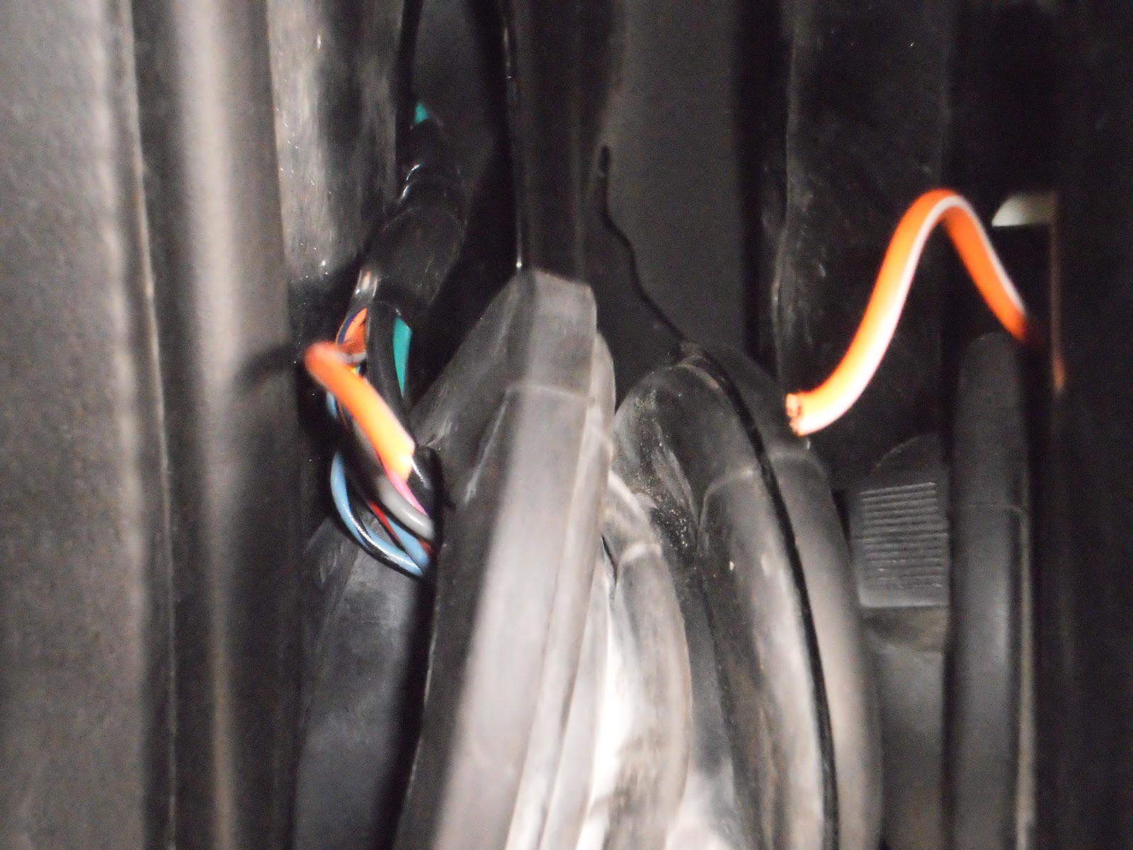
There it is a broken feed wire in the passenger side bellows between door and A pillar. Checking the other wires in the harness and they were all good. A quick repair of the wire and reassembly and all is well. The RKE worked like a charm as well. The shop owner was more than happy. This car was fixed with no parts and quickly. It is a bit unusual to see this sort of failure on the passenger side. I see it all the time on the drivers side however. Think about how many more times you open the drivers side versus the passenger side.
This blog will explore the world of automotive diagnostics. We will show a new case study every week.I will also offer my opinions on various issues in the automotive world.
Sunday, February 19, 2012
Wednesday, February 1, 2012
2002 Saturn L300
Here is a 2002 Saturn L300 with 78,865 miles on it. The complaint here is no air conditioner compressor operation. The shop already did some testing and came up empty. They needed answers fast. I start the car and turn on the air conditioning. I do not hear the click of the AC compressor turning on. At this point I break out the Tech2 knowing full well that the AC compressor control is PCM controlled. Here is some data that I captured.
So here is the data capture. I am really only interested in 3 items at this point.
Here they are. From these 3 pids I can determine the following; It has or thinks it has freon, the PCM is allowing AC operation, and the PCM wants to turn on the AC relay that controls clutch operation on the AC compressor. So now I can concentrate on checking the "muscle" of the system because the "brains" seem to be working properly.
Looking at the actual AC compressor. The compressor clutch looks a bit worn and rusty. At this point I would like to get an available voltage reading at the clutch. Unfortunately, due to the placement in the vehicle I will have to go downstream to get my readings.
Here, I have the compressor clutch power and ground backprobed at the most accesible area closest to the actual compressor. Well, we need to investigate the wiring a bit more. After doing a voltage drop on the ground side of the circuit, I know that our issues are with the power side. Time to get out and review a wiring diagram.
Ok, here we go. We have the typical GM compressor control circuit. The main players are the 10amp A/C fuse and the A/C relay. I didn't go after the control side of the relay because there were no circuit codes that typically set when the control side of the relay is not intact. So let's get to the underhood fusebox.
Checking the A/C fuse and low and behold it was blown. This is going to be easy. Inserting a fresh fuse and it immediately blows when the compressor is supposed to engage. Alright, I was suspicious of the ac compressor clutch all along. So I reach underneath and disconnect the connector right at the compressor clutch and try a fresh fuse and guess what it blows as well. Now, I am down 2 fuses. I have a rule with checking shorts. If I blow 3 fuses it is time for me to put a circuit breaker in place of the fuse. I hate having to do this. I look at the wiring harness and inspect closely. It does not appear to have any obvious damage, such as from a front end hit. My mind starts to wonder is there some type of hidden gremlin on this car and I am going to be pulling harnesses apart for the afternoon? When this happens I take a breath and go back to the wiring diagram. I try to KISS (Keep it simple stupid).
Looking back at the diagram I see there is a diode on the power side of the relay. This diode is there to suppress voltage spikes when the compressor clutch releases. One side of the diode is on the power side and the other is right to ground. I know others were in here testing before me. Could I have a biased diode? Basically, a direct short to ground. Let's test.
I remove the diode and hook up my meter leads to the diode terminals. Set the meter to diode test. The diode test will do a voltage drop test across the diode. With the meter leads one way I should see approximately a half of volt (0.50v) then reverseing the "polarity" of the leads on the diode should net us an open circuit. Let's see what we got.
Yikes! Let's reverse the leads.
Double Yikes! Basically this diode is now a direct short to ground. It is now a paperclip instead of a semiconductor. Luckily, this shop owner had a GM car that was going to the boneyard. I quickly stole the diode out of the fusebox. Let's test that one.
Ok. Let's reverse the leads.
Nice. Textbook. I install the good used ac diode. I turn on the ac and listen for that familiar click from the compressor. I hear nothing. What now? I recheck the fuse-good. Rehooking up my meter leads at the compressor clutch wires I am greeted to this.
So, I now have correct voltage feed. But, still no operation. Remember, that compressor clutch I suspected all the while.
I instruct the shop to drop the compressor. Here, is the clutch coil resistance 4.69M ohms basically an open circuit. Normal clutch coil resistance is 3.22 ohms. There is a thermal fuse incorporated in the clutch coil that will open at 417F. Once this opens up there is no going back-replacement is necessary. My guess here is the compressor clutch overheated. I think the diode failure was previous tester error. Someone got happy with the power probe. The lesson here is keep cool when there are multiple issues.
So here is the data capture. I am really only interested in 3 items at this point.
Here they are. From these 3 pids I can determine the following; It has or thinks it has freon, the PCM is allowing AC operation, and the PCM wants to turn on the AC relay that controls clutch operation on the AC compressor. So now I can concentrate on checking the "muscle" of the system because the "brains" seem to be working properly.
Looking at the actual AC compressor. The compressor clutch looks a bit worn and rusty. At this point I would like to get an available voltage reading at the clutch. Unfortunately, due to the placement in the vehicle I will have to go downstream to get my readings.
Here, I have the compressor clutch power and ground backprobed at the most accesible area closest to the actual compressor. Well, we need to investigate the wiring a bit more. After doing a voltage drop on the ground side of the circuit, I know that our issues are with the power side. Time to get out and review a wiring diagram.
Ok, here we go. We have the typical GM compressor control circuit. The main players are the 10amp A/C fuse and the A/C relay. I didn't go after the control side of the relay because there were no circuit codes that typically set when the control side of the relay is not intact. So let's get to the underhood fusebox.
Checking the A/C fuse and low and behold it was blown. This is going to be easy. Inserting a fresh fuse and it immediately blows when the compressor is supposed to engage. Alright, I was suspicious of the ac compressor clutch all along. So I reach underneath and disconnect the connector right at the compressor clutch and try a fresh fuse and guess what it blows as well. Now, I am down 2 fuses. I have a rule with checking shorts. If I blow 3 fuses it is time for me to put a circuit breaker in place of the fuse. I hate having to do this. I look at the wiring harness and inspect closely. It does not appear to have any obvious damage, such as from a front end hit. My mind starts to wonder is there some type of hidden gremlin on this car and I am going to be pulling harnesses apart for the afternoon? When this happens I take a breath and go back to the wiring diagram. I try to KISS (Keep it simple stupid).
Looking back at the diagram I see there is a diode on the power side of the relay. This diode is there to suppress voltage spikes when the compressor clutch releases. One side of the diode is on the power side and the other is right to ground. I know others were in here testing before me. Could I have a biased diode? Basically, a direct short to ground. Let's test.
I remove the diode and hook up my meter leads to the diode terminals. Set the meter to diode test. The diode test will do a voltage drop test across the diode. With the meter leads one way I should see approximately a half of volt (0.50v) then reverseing the "polarity" of the leads on the diode should net us an open circuit. Let's see what we got.
Yikes! Let's reverse the leads.
Double Yikes! Basically this diode is now a direct short to ground. It is now a paperclip instead of a semiconductor. Luckily, this shop owner had a GM car that was going to the boneyard. I quickly stole the diode out of the fusebox. Let's test that one.
Ok. Let's reverse the leads.
Nice. Textbook. I install the good used ac diode. I turn on the ac and listen for that familiar click from the compressor. I hear nothing. What now? I recheck the fuse-good. Rehooking up my meter leads at the compressor clutch wires I am greeted to this.
So, I now have correct voltage feed. But, still no operation. Remember, that compressor clutch I suspected all the while.
I instruct the shop to drop the compressor. Here, is the clutch coil resistance 4.69M ohms basically an open circuit. Normal clutch coil resistance is 3.22 ohms. There is a thermal fuse incorporated in the clutch coil that will open at 417F. Once this opens up there is no going back-replacement is necessary. My guess here is the compressor clutch overheated. I think the diode failure was previous tester error. Someone got happy with the power probe. The lesson here is keep cool when there are multiple issues.
Sunday, January 15, 2012
Happy New Year 2012
First off I want to wish everyone a happy and prosperous new year. I am hoping for great things in the coming year. I want to especially thank all my customers for their business and wish them continued success. I also hope to pickup some new customers in 2012.
I would also like to start off 2012 with a great story. One of my customers is Pride Automotive in Patchogue. Tony and his son Anthony are great people and run a very honest automotive repair business. They organize an annual food drive for the less fortunate around Thanksgiving. Which I am proud to say my family and I contributed to this year. Right around Christmas time Tony was presented with a dilemma. He received a phone call from a Marine officer who was trying to help out a fellow Marine. The dilemma goes something like this. This female Marine needed a car. She basically got taken over the coals by an employee of a used car lot. This employee sold a car on the side from his private stock and without consent from his boss. This car a 1990 Nissan Sentra sadly lasted a week before the engine failed. When this Marine went back to the used car dealer the employee was nowhere to be found, the deal was not legitimate, and now no recourse. So, now this Marine was out of money and out of car. Tony a fellow serviceman having served in the United States Coast Guard decided to lend a hand. After getting the car to his shop he assessed it indeed needed an engine replacement. This Nissan Sentra was super clean and other than a bad engine was in decent shape. At this point Tony had to find an engine and make some hard decisions. Well, what Tony did deserves some accolades. He not only purchased a used engine on his own dime. He also installed it, replaced the radiator (which was clogged solid and probably the reason for the engine failure), and gave it a tune up. All this at no cost to this fellow serviceman, uh servicewoman. This represents the good in the automotive repair and something that mainstream news would never report. Something, I was glad to see. Good job Tony!
Monday, December 19, 2011
2002 Chevrolet Monte Carlo
A bright yellow 2002 Chevrolet Monte Carlo 3.8 liter with 117,263 miles on the odometer is at Mr. T's shop. The vehicle came in as a no start, no crank condition. The battery load tested bad so a new battery went in with the same result. I am informed that they can jump out the starter relay and the car will crank but will not stay running. Let's look at the starter circuit for starters.
Ok we have a starter relay which is called out as a crank relay in this diagram. The relay is PCM controlled. The PCM will engage the relay when it sees a crank voltage input and the gear input is correct. We don't want the vehicle cranking when in gear. But, there is one more piece of the puzzle. Lets look at some theory.
This is some Passlock (the vehicle theft system) theory from GM. I underlined the parts that pertain to our issue at hand. Passlock has been around since 1995/1996 on GM vehicles. On some years/models it will disable the starter relay operation and other years it won't. Check the description of operation if you are not sure. I know what I am doing next.
I hook up my Tech2 and perform a Class 2 DTC check. I use this to see what modules are reporting on the Class 2 data line. I see an issue here already. There is a module that is linked to our problem that is not here. The BCM is AWOL. Now, we have to find out why. I check the fuses that power up the BCM in the left side instrument panel fusebox which are good. My next step is to see if there is any add on items such as an aftermarket alarm that would be causing issues with the BCM.
The BCM is located under the left side of the dash buried up high. There is an aftermarket alarm involved that dropped on me as I dropped this panel. I disconnected the aftermarket alarm module and rechecked to see if the BCM came back online. No dice. We have to get right at the BCM.
There it is tucked up high. I wrestle it down and backprobed the powers and grounds right at the BCM they are fine. The next thing I do is to disconnect all the connectors at the BCM and walk away from the vehicle for 20 minutes. I return and reconnect the BCM. Let's recheck to see if now the BCM is reporting.
Well look at this. The BCM is back online. The car starts and runs now. This is what is called "logic lock" in the industry. The module was electrically locked and shutdown. Disconnecting it for 20 minutes and reconnecting unlocked it. I have seen this on Chrysler and Nissan vehicles as well as GM vehicles. There is much debate about what causes this and what is the proper repair. I believe logic lock is caused by voltage fluctuations, surges, spikes, or excessive ac voltage ripple. In this case I believe the weak battery caused the logic lock. I did check charging rate and for ac ripple as well. Now, the proper repair some believe would be to change the locked module for fear it will lock again. The theory there is that the module lock is a symptom of a bad module. I give the shop owner the options. He decides to let it go as is and to inform the customer of the possibilities. This vehicle has been out now for a month and doing just fine.
Ok we have a starter relay which is called out as a crank relay in this diagram. The relay is PCM controlled. The PCM will engage the relay when it sees a crank voltage input and the gear input is correct. We don't want the vehicle cranking when in gear. But, there is one more piece of the puzzle. Lets look at some theory.
This is some Passlock (the vehicle theft system) theory from GM. I underlined the parts that pertain to our issue at hand. Passlock has been around since 1995/1996 on GM vehicles. On some years/models it will disable the starter relay operation and other years it won't. Check the description of operation if you are not sure. I know what I am doing next.
I hook up my Tech2 and perform a Class 2 DTC check. I use this to see what modules are reporting on the Class 2 data line. I see an issue here already. There is a module that is linked to our problem that is not here. The BCM is AWOL. Now, we have to find out why. I check the fuses that power up the BCM in the left side instrument panel fusebox which are good. My next step is to see if there is any add on items such as an aftermarket alarm that would be causing issues with the BCM.
The BCM is located under the left side of the dash buried up high. There is an aftermarket alarm involved that dropped on me as I dropped this panel. I disconnected the aftermarket alarm module and rechecked to see if the BCM came back online. No dice. We have to get right at the BCM.
There it is tucked up high. I wrestle it down and backprobed the powers and grounds right at the BCM they are fine. The next thing I do is to disconnect all the connectors at the BCM and walk away from the vehicle for 20 minutes. I return and reconnect the BCM. Let's recheck to see if now the BCM is reporting.
Well look at this. The BCM is back online. The car starts and runs now. This is what is called "logic lock" in the industry. The module was electrically locked and shutdown. Disconnecting it for 20 minutes and reconnecting unlocked it. I have seen this on Chrysler and Nissan vehicles as well as GM vehicles. There is much debate about what causes this and what is the proper repair. I believe logic lock is caused by voltage fluctuations, surges, spikes, or excessive ac voltage ripple. In this case I believe the weak battery caused the logic lock. I did check charging rate and for ac ripple as well. Now, the proper repair some believe would be to change the locked module for fear it will lock again. The theory there is that the module lock is a symptom of a bad module. I give the shop owner the options. He decides to let it go as is and to inform the customer of the possibilities. This vehicle has been out now for a month and doing just fine.
Sunday, December 11, 2011
2001 Nissan Sentra
This 2001 Nissan Sentra 1.8 liter with 216,173 miles on it rolled into this shop with the MIL on and running rough. The car's owner "diagnosed" it as a bad fuel injector because he had trouble with injectors before. The shop owner called me in to confirm or disprove the customers "driveway diagnosis". I start the car up and indeed it runs rough and has a MIL on. Lets check the code for starters and then roll up the sleeves.
Ok, we got something to go on. I have a P0303 code for cylinder #3 misfire. I am thankful for this because Nissan on the whole usually sets a P0300 code for multiple misfires rather than specific cylinders. Either way we need to confirm if the PCM is telling the truth about which cylinder is misfiring and then find out why it is misfiring. Whenever possible I like to backup what the PCM is telling me. So......
My scanner allows me to do a power balance test. When I select a cylinder I can disable that cylinder and check for contribution. I am looking for rpm drop when the cylinder is killed and I am looking to feel the engine running change as the cylinder is disabled. Here I disable #3 cylinder and the rpm doesn't drop and I do not feel any change in how the vehicle is running. I always try a known good cylinder to compare and check whether my scanner is doing as advertised.
Here I do the same procedure with #1 cylinder. I get a substantial rpm drop and the vehicle runs much differently with #1 cylinder disabled. So, now we know we have a true blue problem with #3 cylinder. What's next?
This Sentra is a California emissions vehicle. It uses two upstream oxygen sensors to monitor fuel control. Oxygen sensor 1 is bank 1 that monitors cylinders #1 and #4. Oxygen sensor 2 is bank 2 that monitors cylinders #2 and #3. Important to know when we look at fuel trims. Just a FYI there was a CA (Clean Air) version that had one Air Fuel ratio sensor upstream instead of two oxygen sensors. Know which emission standard you have when doing testing.
Here are the fuel trims for this vehicle at an idle. Nissan uses what is called Alpha for fuel trim. Basically 0 Alpha is perfect fuel control. Nissan actually displays true 0 Alpha as 100. The Ottotest interprets it a bit differently. But, it serves the purpose. Whenever I have a misfire I always look at fuel trims. They can give you clues to where to go next and zero in on your problem. Remember, my job is to diagnose quickly and accurately. I see nothing here that would tell me that this vehicle suffers from a fuel injector issue. If the fuel injector was plugged or inoperative I would expect to see exaggerated numbers in the positive range as the PCM tries to compensate for the lack of fuel. The exact opposite would happen if the injector was leaking. At this point I am not looking at a fuel related misfire.
Those of you that know how I operate should not be suprised by the next step. Out comes the scope and low amp probe. I need to look at the ignition system. This year utilized 4 COP (Coil on plug) units. First our problem cylinder.
Yeesh! Here we have a textbook example of a shorted coil. The turn on portion of the pattern goes straight up. No turn on oscillations at the beginning of the pattern (more on primary current and turn on oscillations later this month). Let's check a known good cylinder.
Notice the difference. A nice sloping turn on with turn on oscillations at the very beginning of the turn on pattern. This vehicle has a bad COP unit on #3 cylinder. Let's check that #3 injector to satisfy the customer and shop owner.
Looks good to me. Nice pattern with about 4.0ms of on time. A nice injector turn off spike and we know it is not clogged due to the "pintle hump". Let me point out the pintle hump.
This is the pintle hump. This is the actual mechanical closing of the injector viewed through the scope. No pintle hump and typically the injector is clogged or damaged mechanically. Some pintle hump injector patterns will not be so defined. It is something I look at when looking at injector scope patterns. I inform the shop owner to get a quality COP unit and spark plug for #3 cylinder. I also advise to check the rest of the plugs as well.
Just to go the low tech route as well I put my open gap style spark tester on #3 COP unit start the vehicle and we have no spark.
Ok, we got something to go on. I have a P0303 code for cylinder #3 misfire. I am thankful for this because Nissan on the whole usually sets a P0300 code for multiple misfires rather than specific cylinders. Either way we need to confirm if the PCM is telling the truth about which cylinder is misfiring and then find out why it is misfiring. Whenever possible I like to backup what the PCM is telling me. So......
My scanner allows me to do a power balance test. When I select a cylinder I can disable that cylinder and check for contribution. I am looking for rpm drop when the cylinder is killed and I am looking to feel the engine running change as the cylinder is disabled. Here I disable #3 cylinder and the rpm doesn't drop and I do not feel any change in how the vehicle is running. I always try a known good cylinder to compare and check whether my scanner is doing as advertised.
Here I do the same procedure with #1 cylinder. I get a substantial rpm drop and the vehicle runs much differently with #1 cylinder disabled. So, now we know we have a true blue problem with #3 cylinder. What's next?
This Sentra is a California emissions vehicle. It uses two upstream oxygen sensors to monitor fuel control. Oxygen sensor 1 is bank 1 that monitors cylinders #1 and #4. Oxygen sensor 2 is bank 2 that monitors cylinders #2 and #3. Important to know when we look at fuel trims. Just a FYI there was a CA (Clean Air) version that had one Air Fuel ratio sensor upstream instead of two oxygen sensors. Know which emission standard you have when doing testing.
Here are the fuel trims for this vehicle at an idle. Nissan uses what is called Alpha for fuel trim. Basically 0 Alpha is perfect fuel control. Nissan actually displays true 0 Alpha as 100. The Ottotest interprets it a bit differently. But, it serves the purpose. Whenever I have a misfire I always look at fuel trims. They can give you clues to where to go next and zero in on your problem. Remember, my job is to diagnose quickly and accurately. I see nothing here that would tell me that this vehicle suffers from a fuel injector issue. If the fuel injector was plugged or inoperative I would expect to see exaggerated numbers in the positive range as the PCM tries to compensate for the lack of fuel. The exact opposite would happen if the injector was leaking. At this point I am not looking at a fuel related misfire.
Those of you that know how I operate should not be suprised by the next step. Out comes the scope and low amp probe. I need to look at the ignition system. This year utilized 4 COP (Coil on plug) units. First our problem cylinder.
Yeesh! Here we have a textbook example of a shorted coil. The turn on portion of the pattern goes straight up. No turn on oscillations at the beginning of the pattern (more on primary current and turn on oscillations later this month). Let's check a known good cylinder.
Notice the difference. A nice sloping turn on with turn on oscillations at the very beginning of the turn on pattern. This vehicle has a bad COP unit on #3 cylinder. Let's check that #3 injector to satisfy the customer and shop owner.
Looks good to me. Nice pattern with about 4.0ms of on time. A nice injector turn off spike and we know it is not clogged due to the "pintle hump". Let me point out the pintle hump.
This is the pintle hump. This is the actual mechanical closing of the injector viewed through the scope. No pintle hump and typically the injector is clogged or damaged mechanically. Some pintle hump injector patterns will not be so defined. It is something I look at when looking at injector scope patterns. I inform the shop owner to get a quality COP unit and spark plug for #3 cylinder. I also advise to check the rest of the plugs as well.
Just to go the low tech route as well I put my open gap style spark tester on #3 COP unit start the vehicle and we have no spark.
More pictures of "chia pet" modules
Remember last time when I told you about another van that had an EPA issue. Well here it is after the shop helper cleaned it with some bleach. Remember, this is after!
Here is the vinyl mat lifted up. The helper did an excellent job of cleaning. This vehicle is going to need at the very least a new SDM, setup, and repair of the rotted harness.
Monday, November 28, 2011
2002 GMC Savana 2500 Diesel
Ok. Let me start off by apologizing for not posting in awhile. I have been very busy thankfully. I will be updating more often. I have here a nice 2002 GMC Savana 6.5 liter diesel van with 99,859 on the odometer. I am called in after this shop put a motor in and wants to set injector pump timing. They hook up the shop scanner and get no communication. That is when they called me in. I get the same result with my Tech2 scantool. The vehicle starts and runs, so I know something is going on. I poll the modules with my Tech2 and can only communicate with the vehicle theft deterrent module. Lets look at how this system works.
This system utilizes what is called Class 2 communication. Think of it like a telephone line. This line is where modules communicate with each other and with a technician through pin #2 of the data link connector. Each module on Class 2 has the ability to communicate all on it's own. It is what is known as a peer to peer system. It doesn't need a "master" module to work.
Here, I circled the players involved on this vehicle. Since I can communicate with the theft module I know I have some Class 2 communication. I have been down this road before. There are two common modules I see that cause Class 2 issues. They are the ABS module, the SRS (Air Bag) module, and their related wiring. The quick and dirty on these problems is disconnect modules one at a time and see if the remaining modules start talking. So, I put the van up in the air and disconnect the ABS module on the frame rail and recheck Class 2 comunication-no dice. Still only the vehicle theft module reporting.
Now, the SRS module is under the drivers seat. Here is a shot from the passenger side. GM puts a one piece vinyl mat down throughout the front floor of these vehicles. This mat goes under the seats and over the the top of the SRS module. This vinyl mat is great for holding moisture underneath it. These vans all have water intrusion issues. If the fusebox and PCM isn't filling up with water, the windshield is leaking and causing water to collect especially under the driver's seat. So, we are left with taking the front seats out and peeling the vinyl mat back or slitting the mat around the SRS module with a razor to do some inspection. I get the ok to slice and dice and this is what I see.
Holy corrosion! I have seen these pretty bad, but this by far was the worst. The SDM (Sensing and Diagnostic Module) and it's connector are chia pets! Here is another shot.
I try to disconnect the connector from the SDM and will not budge. In fact, the shell comes off in my hand and the terminals are corroded to the module. Hard decisions need to be made here. I will have to cut this harness to see if we get communication back. I also give a sneak peek to the harness that is running back from the SDM to the front as they frequently corrode as well from trapped moisture. It doesn't look that bad, so I snip the SDM harness and now we have 5 modules reporting on Class 2. SDM, PCM, Radio, Vehicle Theft, and ABS. Now, that I am able to communicate with the PCM we check and adjust injector pump timing as per GM specifications.
Here is a scope pattern of Class 2 after we snipped trhe SDM harness and got the other modules back on line. I should have taken a capture before snipping the SDM harness. I guarantee you that it didn't look anything like this. This is a nice healthy Class 2 pattern. Nice well defined square waves that are 7 volts in amplitude and are off ground approximately 200mv for less noise. The square waves come in "data packets" as modules send signals to one another. What is funny is that the week before this job I was at another shop with a similiar problem. Someone had an aftermarket radio shoved in it and I was very suspicious that the shoddy radio install was causing issues. I pulled the radio out and was shining a light in there and noticed strong evidence of rodents-seeds, acorns, droppings, and chewed wires. Still shining my light in this area I was also greeted by roaches! At this point I fled the vehicle and informed the shop owner he needed an exterminator for the vermin and roach problem his customers van had. The next day another shop had van issues and lifting up the vinyl floor mat revealed a rotted harness and black stringy mold. At that point I informed the shop owner he had a EPA issue with that van. You never know what you are going to find.
This system utilizes what is called Class 2 communication. Think of it like a telephone line. This line is where modules communicate with each other and with a technician through pin #2 of the data link connector. Each module on Class 2 has the ability to communicate all on it's own. It is what is known as a peer to peer system. It doesn't need a "master" module to work.
Here, I circled the players involved on this vehicle. Since I can communicate with the theft module I know I have some Class 2 communication. I have been down this road before. There are two common modules I see that cause Class 2 issues. They are the ABS module, the SRS (Air Bag) module, and their related wiring. The quick and dirty on these problems is disconnect modules one at a time and see if the remaining modules start talking. So, I put the van up in the air and disconnect the ABS module on the frame rail and recheck Class 2 comunication-no dice. Still only the vehicle theft module reporting.
Now, the SRS module is under the drivers seat. Here is a shot from the passenger side. GM puts a one piece vinyl mat down throughout the front floor of these vehicles. This mat goes under the seats and over the the top of the SRS module. This vinyl mat is great for holding moisture underneath it. These vans all have water intrusion issues. If the fusebox and PCM isn't filling up with water, the windshield is leaking and causing water to collect especially under the driver's seat. So, we are left with taking the front seats out and peeling the vinyl mat back or slitting the mat around the SRS module with a razor to do some inspection. I get the ok to slice and dice and this is what I see.
Holy corrosion! I have seen these pretty bad, but this by far was the worst. The SDM (Sensing and Diagnostic Module) and it's connector are chia pets! Here is another shot.
I try to disconnect the connector from the SDM and will not budge. In fact, the shell comes off in my hand and the terminals are corroded to the module. Hard decisions need to be made here. I will have to cut this harness to see if we get communication back. I also give a sneak peek to the harness that is running back from the SDM to the front as they frequently corrode as well from trapped moisture. It doesn't look that bad, so I snip the SDM harness and now we have 5 modules reporting on Class 2. SDM, PCM, Radio, Vehicle Theft, and ABS. Now, that I am able to communicate with the PCM we check and adjust injector pump timing as per GM specifications.
Here is a scope pattern of Class 2 after we snipped trhe SDM harness and got the other modules back on line. I should have taken a capture before snipping the SDM harness. I guarantee you that it didn't look anything like this. This is a nice healthy Class 2 pattern. Nice well defined square waves that are 7 volts in amplitude and are off ground approximately 200mv for less noise. The square waves come in "data packets" as modules send signals to one another. What is funny is that the week before this job I was at another shop with a similiar problem. Someone had an aftermarket radio shoved in it and I was very suspicious that the shoddy radio install was causing issues. I pulled the radio out and was shining a light in there and noticed strong evidence of rodents-seeds, acorns, droppings, and chewed wires. Still shining my light in this area I was also greeted by roaches! At this point I fled the vehicle and informed the shop owner he needed an exterminator for the vermin and roach problem his customers van had. The next day another shop had van issues and lifting up the vinyl floor mat revealed a rotted harness and black stringy mold. At that point I informed the shop owner he had a EPA issue with that van. You never know what you are going to find.
Subscribe to:
Posts (Atom)