That is right a Bimmer. Now, I don't normally even touch these cars but I dabble from time to time. This is one of those times one of my good customers has this pretty clean BMW with 181,582 miles on it. Apparently, it had a Check Engine Lamp on and one of his techs pulled a P0171 (System Lean) code. When I get there the codes and more importantly the freeze frame data has been cleared. Since I don't normally diagnose these cars, all I can use is generic scantool data. So I focus in on our fuel trims and MAF (Mass Air Flow) sensor inputs. I know these have common issues with MAF sensors and Ventilation valves causing lean codes. I check fuel trims at an idle and they are pretty tight, raced up they start to drift into the positive side. I figure slam dunk I have a dirty MAF.
Looking at the MAF hot wire it is really clean and the customer has a factory BMW air filter. No cheapy air filter here. So, no slam dunk here. A road test is in order. I monitor short term fuel trim, rpm, and MAF g/s values. I am still thinking bad MAF here. The peak g/s easily achieves our liter displacement times 40 rule of thumb and short term fuel trims do not follow air flow. The one thing I do notice during the test drive is a distinct whistle on wide open throttle. Hmmm. Experience tells me when I hear a whistle it is usually caused by an intake restriction or some type of hole in the air tract. Since I already inspected the air box and it has a quality air filter installed. I head to the air ducting after the MAF sensor.
Bingo! Now I am a BMW expert. No way! A seasoned BMW tech would have probably found this in half the time. Here is another shot below.
The point here is some strategic testing even in generic mode and we can fix cars we are not exactly familiar with. I report my findings to the shop owner and advised him to change that much maligned ventilation valve with the updated one as maintenance considering the mileage on this car. I also advise him of Standard Motor Products new line called TechSmart that my good buddy Joe Donaggio manages. This new line is all previously dealer only, high failure, problem solving parts like these ventilation valves. It is a great alternative to going back to the dealer. I and others give Joe constant feedback from the technical "real" world and he does the leg work to make it happen. Check it out at http://www.techsmartparts.com/.
This blog will explore the world of automotive diagnostics. We will show a new case study every week.I will also offer my opinions on various issues in the automotive world.
Saturday, May 21, 2011
Sunday, May 15, 2011
2005 GMC Yukon Denali
This is a nice 2005 GMC Yukon with 156K miles on it, I am asked to look at on this nice and sunny morning. The customer complaint is that the Service Engine Soon lamp illuminates. I start the truck up and it runs quite well and the lamp is not on presently. I scan for current codes and get none. Scanning for history codes I get a P0171 (System lean bank 1), P0174 (System lean bank 2), and a P0101 (Mass Air Flow Performance). Now at this point most techs would say put a mass air flow sensor in it and send it on it's way. I need to be absolutely sure before I stick my neck out. So many factors could cause these codes from weak fuel pumps to glitchy connections at the mass air flow sensor to damaged air filters causing turbulence that would affect the mass air flow sensors calculations. So the first thing I do is a visual. You never know what you are going to find with your eyes.
Nothing amiss here. I check the air filter for fit and function as well as the air ducting. All seems to be in good working order. The mass air flow sensor is installed correctly as well. There are certain GM applications where the mass air flow can be installed incorrectly. There are arrows on the sensor indicating flow direction. I also look to see if there are any aftermarket air flow ducting, air filters, etc and make notes of it. It wouldn't be the first time I have seen the $450.00 chrome billet air flow tube that was supposed to give you 65 more horsepower causing issues such as this. Alright time to look at some scan data. These new generation GM V-8 motors have had their fair share of intake manifiold gasket issues. Looking at fuel trims at an idle and raced up show some pretty tight fuel control. Plus, looking at some freeze frame and failure records show me these codes set at mid range rpm's with the engine fully warmed up. Typical intake manifold gasket issues rear their heads more at low speeds and low engine temperatures.
Time to take a test drive. If you have been following my blog you know that I have been beating up my new scanner the Ottotest pretty bad. I decided to use it on this vehicle because of it's excellent graphing capabilities.
The above is part of a graph I did on the road test. Remember, click on the pics to enlarge. I graphed mass air flow sensor grams per second, short term fuel trims for both banks, and power enrichment mode. I took actual photos of these screen shots for two reasons. One, I wanted to show you the multi colored graph which is very cool. The second is that when you save the graph on Ottotest to export, it is a xps file that is black and white. Something I hope they fix. Saving it on the Ottotest retains the color, you can also scroll after the fact, as well as play with the cursors. The above screen shot is meant to show you the relationship betwen air flow and short term fuel trim. The actual numbers on the right reflect cursor 1, which isn't even on any event in this field so diregard for right now. Here is another screenshot below.
Do you notice something yet? Short term fuel trims follow air flow. When air flow increases fuel trims increase. It may be hard to see due to the graph scaling. In the above screenshot the cursor is on this screen and on frame 792, so the numbers on the right are correct. Let's zoom in and recheck something the Ottotest does really well.
Now it becomes more apparent. remember this is a normal test drive. Whenever, you have fuel trims following air flow you have an air measuring error. Remember, that an air measuring error is conditional on proper air ducting, filtration, etc. Now what? Do we call a bad mass air flow sensor? Not yet. I always like to do a couple of wide open throttle runs at speed and record some parameters to calculate volumetric efficiency. So changing my parameters to graph. I go with engine rpm, mass air flow sensor g/s, intake air temperature, and power enrichment.
Here is a screen shot of a wot (wide open throttle event). Remember, the cursor is all the way at an idle event see the rpm and low g/s. I wanted to illustrate a full from idle to wot event. I always get asked what is a good g/s reading at an idle? At wot? Well, there are no hardfast rules but g/s at an idle should equal your liter displacement on anything over 2.5 liters. Wot readings should be your liter dispacement times 40 as a general rule. This 6.0 liter had a value of 7-8 g/s at an idle. Lets look at some more data.
To figure out VE (Volumetric Efficiency) you need these parameters and use your highest g/s reading. Here I snuck up on it with my cursor. Given our rule of thumb is this reading low or correct for this vehicle? Looks a bit low since we should be seeing close to 240 g/s at wide open throttle. But, lets let the VE calculator be the judge. You can find VE calculator downloads all over-some free-some not. Let's do some calculations.
Engine Size (Cid)-366.15
Engine Rpm-5048
G/S-178
Intake Air Temp (F)-96.8
Volumetric Efficiency-61.667%
A good VE for a naturally aspirated engine is 80% or better. Any type of forced induction should net you 100% or better. We are well below our 80% goal at 61.667%. Let's see what happens when we add our theoretical proper g/s value.
Engine Size (Cid)-366.15
Engine Rpm-5048
G/S-240
Intake Air Temp (F)-96.8
Volumetric Efficiency-83.146%
So, there may be some truth in that value. I always take a couple of wot runs and check a bunch of them. Here is another.
I will zoom in....
Behold, the power of graphing! On the road test the vehicle definitely didn't have the power a 6.0 liter should have and detonated quite badly. I graphed the o2 sensors on wot runs as well just to make sure I wasn't also running out of fuel. They were definitely showing enrichment. Now, I could have gone further and done a low amp probe on the fuel pump circuit as well as fuel pressure and volume tests. But, given the data I had with the customers complaint I was sure we had a bad mass air flow sensor. The detonation is coming from an improper timing schedule due to the under reporting mass air flow sensor. Typically, this is how a mass air flow sensor will fail. It will report correctly at an idle and under report as airflow increases. This is not always the case though. You can have any combination for failure. Oh, by the way I do not agree with cleaning mass air flow sensors to fix them. Cleaning to verify you are going in the right direction-yes. The reason for my thinking is simple. Once you clean that customers mass air flow sensor and it takes care of his problem they are going to think a MAF cleaning is going to fix any issue from check engine lamp to rear brake noise. I report my findings to the shop owner and move on to the next vehicle.
Nothing amiss here. I check the air filter for fit and function as well as the air ducting. All seems to be in good working order. The mass air flow sensor is installed correctly as well. There are certain GM applications where the mass air flow can be installed incorrectly. There are arrows on the sensor indicating flow direction. I also look to see if there are any aftermarket air flow ducting, air filters, etc and make notes of it. It wouldn't be the first time I have seen the $450.00 chrome billet air flow tube that was supposed to give you 65 more horsepower causing issues such as this. Alright time to look at some scan data. These new generation GM V-8 motors have had their fair share of intake manifiold gasket issues. Looking at fuel trims at an idle and raced up show some pretty tight fuel control. Plus, looking at some freeze frame and failure records show me these codes set at mid range rpm's with the engine fully warmed up. Typical intake manifold gasket issues rear their heads more at low speeds and low engine temperatures.
Time to take a test drive. If you have been following my blog you know that I have been beating up my new scanner the Ottotest pretty bad. I decided to use it on this vehicle because of it's excellent graphing capabilities.
The above is part of a graph I did on the road test. Remember, click on the pics to enlarge. I graphed mass air flow sensor grams per second, short term fuel trims for both banks, and power enrichment mode. I took actual photos of these screen shots for two reasons. One, I wanted to show you the multi colored graph which is very cool. The second is that when you save the graph on Ottotest to export, it is a xps file that is black and white. Something I hope they fix. Saving it on the Ottotest retains the color, you can also scroll after the fact, as well as play with the cursors. The above screen shot is meant to show you the relationship betwen air flow and short term fuel trim. The actual numbers on the right reflect cursor 1, which isn't even on any event in this field so diregard for right now. Here is another screenshot below.
Do you notice something yet? Short term fuel trims follow air flow. When air flow increases fuel trims increase. It may be hard to see due to the graph scaling. In the above screenshot the cursor is on this screen and on frame 792, so the numbers on the right are correct. Let's zoom in and recheck something the Ottotest does really well.
Now it becomes more apparent. remember this is a normal test drive. Whenever, you have fuel trims following air flow you have an air measuring error. Remember, that an air measuring error is conditional on proper air ducting, filtration, etc. Now what? Do we call a bad mass air flow sensor? Not yet. I always like to do a couple of wide open throttle runs at speed and record some parameters to calculate volumetric efficiency. So changing my parameters to graph. I go with engine rpm, mass air flow sensor g/s, intake air temperature, and power enrichment.
Here is a screen shot of a wot (wide open throttle event). Remember, the cursor is all the way at an idle event see the rpm and low g/s. I wanted to illustrate a full from idle to wot event. I always get asked what is a good g/s reading at an idle? At wot? Well, there are no hardfast rules but g/s at an idle should equal your liter displacement on anything over 2.5 liters. Wot readings should be your liter dispacement times 40 as a general rule. This 6.0 liter had a value of 7-8 g/s at an idle. Lets look at some more data.
To figure out VE (Volumetric Efficiency) you need these parameters and use your highest g/s reading. Here I snuck up on it with my cursor. Given our rule of thumb is this reading low or correct for this vehicle? Looks a bit low since we should be seeing close to 240 g/s at wide open throttle. But, lets let the VE calculator be the judge. You can find VE calculator downloads all over-some free-some not. Let's do some calculations.
Engine Size (Cid)-366.15
Engine Rpm-5048
G/S-178
Intake Air Temp (F)-96.8
Volumetric Efficiency-61.667%
A good VE for a naturally aspirated engine is 80% or better. Any type of forced induction should net you 100% or better. We are well below our 80% goal at 61.667%. Let's see what happens when we add our theoretical proper g/s value.
Engine Size (Cid)-366.15
Engine Rpm-5048
G/S-240
Intake Air Temp (F)-96.8
Volumetric Efficiency-83.146%
So, there may be some truth in that value. I always take a couple of wot runs and check a bunch of them. Here is another.
I will zoom in....
Behold, the power of graphing! On the road test the vehicle definitely didn't have the power a 6.0 liter should have and detonated quite badly. I graphed the o2 sensors on wot runs as well just to make sure I wasn't also running out of fuel. They were definitely showing enrichment. Now, I could have gone further and done a low amp probe on the fuel pump circuit as well as fuel pressure and volume tests. But, given the data I had with the customers complaint I was sure we had a bad mass air flow sensor. The detonation is coming from an improper timing schedule due to the under reporting mass air flow sensor. Typically, this is how a mass air flow sensor will fail. It will report correctly at an idle and under report as airflow increases. This is not always the case though. You can have any combination for failure. Oh, by the way I do not agree with cleaning mass air flow sensors to fix them. Cleaning to verify you are going in the right direction-yes. The reason for my thinking is simple. Once you clean that customers mass air flow sensor and it takes care of his problem they are going to think a MAF cleaning is going to fix any issue from check engine lamp to rear brake noise. I report my findings to the shop owner and move on to the next vehicle.
Friday, May 13, 2011
Ottotest Update
I have been trying to implement the Ottotest into my diagnostics as much as possible. It seems to have shortcomings every time I use it. I had a 2007 Chevrolet Trailblazer with a Service 4wd lamp on. The Ottotest didn't even recognize the four wheel drive module and I was forced to use the shops own Snap On Solus to retrieve codes for the four wheel drive system. How embarassing! Next up was a no start/no crank on a 2005 Jeep Grand Cherokee. The Ottotest did a great job on retrieving a PCM code of P0513 (Invalid Skim Key) and communicating with all the other modules save one. You guessed it no communication/no menu for the SKREEM (Security) Module. The one module I needed to communicate with, the scanner shut me out. I realize that immobilizer recoding is beyond aftermarket scanner abilities. But, let me in, so I can see if its on the data buss and maybe some parameters. I had to resort to tedious backprobing at the SKREEM Module to verify operation. More time wasted. The tablet is slow. So slow that sometimes if you get impatient with commands you will lock up the program forcing a hard reboot. More time wasted. The battery life is nowhere near advertised. I have been sending feedback to Blue Streak every week. I am starting to think this tool was not as advertised and it has cost me money rather than making it. Time will tell.
Monday, April 25, 2011
P0420, P0430, P0421 Catalyst Efficiency Codes
So many techs fear these group of codes because they have been bitten before by them. In my opinion, these are some of the easier codes to solve if you attack it systematically. The first step is to know the enemy. The general code set criteria is as follows; When the the downstream oxygen sensor is within 80% of the activity of the upstream oxygens sensor during a catalyst test the code is set. The key to this is graphing our scan data. Years ago scan data was much too slow to trust graphing it. But, todays datastreams and professional scantools make this a trustworthy venture. Here is a snapshot of`data that was graphed.
In the above we have the following pids graphed. Engine speed, upstream oxygen sensor, downstream oxygen sensor, and throttle position voltage. As you can see we are raced up at 2514 rpm. Is this catalytic converter doing a good job right now? No, not really at all. What I stress here is look at the symmetry between upstream and downstream sensors. They are almost identical. Are we within 80% activity? Looks like it. Now, before you plunk that money down for a catalytic converter there is a couple of things to do. I always take the car for a thorough test drive and recheck oxygen sensor activity out on the road. There are many converters that need a hard test drive to verify operation or "light off". The other test procedure I do is either introduce carb spray or propane into the system to make sure both upstream and downstream oxygen sensors go full rich. Sometimes, I can get away with just "flashing" the throttle a couple of times and checking. Confirm that the vehicle is at operating temperature-bad thermostats, radiator flow, or improper fan operation can play havoc with catalyst operation. The final item to check is fuel trim. Make sure your fuel trims are tight. Fuel trims that are elevated either way will cause catalyst issues.
As you can see in the above snapshot our fuel trims are excellent. Always check fuel trims at an idle, raced up 2500 rpm no load, and at cruise steady throttle out on the road. There is usually a reason behind catalytic converter failure. The reasons can range from a converter that has been digesting misfires, bad fuel trims, and oil contamination. I see the oil contamination issue quite a bit on those pre cat (where the cat is part of the exhaust manifold or directly after the exhaust manifold) vehicles. If you have any of these issues the new converter will go belly up in short order. So now you are ready to order the catalytic converter. Not yet, definitely run a tsb (technical service bulletin) search to see if there are updated parts or reflashing pertaining to your issue. Now you are ready to get prices on the catalytic converter. A call to the OE dealer gives you a price of $842.31-geez the car is only worth $2000.00. A call to the parts house or a converter supplier and the price is $231.28. Why the big difference? First off make sure the aftermarket one is a direct fit. Nothing like giving the cheaper price only to find out you need the $95.00 adaptor kit and have to be Michaelangelo with the welder to get this to fit. The second is make sure that the converter you are getting is OBD2 C.A.R.B (California Air Research Board) certified and they can supply the paperwork supporting this. I have seen too many times the shop sells the cheap converter only to have me come back multiple times and the converter to be exchanged two times before it is realized this cheap converter is in fact cheap. I have also seen where the manufacturer will hide behind that the fuel trim is off, the vehicle is not reaching operating temperature, the oxygen sensors are incorrect when there is a problem. This is why I always document everything. There are certain vehicles I do not recommend aftermarket catalytic converters on period. They are 2001 and up GM cars, Honda vehicles, and Subaru vehicles. It seems the aftermarket cannot make the proper converter for these applications, you get what you pay for.
Another item to be wary of is exhaust leaks ahead of the catalytic converter on codes that never seem to be fixed. An exhaust leak ahead of the converter no matter small will introduce outside oxygen into the exhaust stream. Causing problems and ruin your day. A smoke machine can be used to find small leaks. So what if you have a A/F ratio sensor upstream instead of a conventional sensor. Just look at the downstream sensor graphed and use the hints I have given to diagnose these cars. Most techs think that the catalyst monitor is run during steady highway speeds. That is true of most cars. But, late model GM vehicles will run it at an idle after a highway run. Know your enemy, check your drive cycle routines to determine when it looks at converter status. I hope this helps the next time you have one of these in your bay.
In the above we have the following pids graphed. Engine speed, upstream oxygen sensor, downstream oxygen sensor, and throttle position voltage. As you can see we are raced up at 2514 rpm. Is this catalytic converter doing a good job right now? No, not really at all. What I stress here is look at the symmetry between upstream and downstream sensors. They are almost identical. Are we within 80% activity? Looks like it. Now, before you plunk that money down for a catalytic converter there is a couple of things to do. I always take the car for a thorough test drive and recheck oxygen sensor activity out on the road. There are many converters that need a hard test drive to verify operation or "light off". The other test procedure I do is either introduce carb spray or propane into the system to make sure both upstream and downstream oxygen sensors go full rich. Sometimes, I can get away with just "flashing" the throttle a couple of times and checking. Confirm that the vehicle is at operating temperature-bad thermostats, radiator flow, or improper fan operation can play havoc with catalyst operation. The final item to check is fuel trim. Make sure your fuel trims are tight. Fuel trims that are elevated either way will cause catalyst issues.
As you can see in the above snapshot our fuel trims are excellent. Always check fuel trims at an idle, raced up 2500 rpm no load, and at cruise steady throttle out on the road. There is usually a reason behind catalytic converter failure. The reasons can range from a converter that has been digesting misfires, bad fuel trims, and oil contamination. I see the oil contamination issue quite a bit on those pre cat (where the cat is part of the exhaust manifold or directly after the exhaust manifold) vehicles. If you have any of these issues the new converter will go belly up in short order. So now you are ready to order the catalytic converter. Not yet, definitely run a tsb (technical service bulletin) search to see if there are updated parts or reflashing pertaining to your issue. Now you are ready to get prices on the catalytic converter. A call to the OE dealer gives you a price of $842.31-geez the car is only worth $2000.00. A call to the parts house or a converter supplier and the price is $231.28. Why the big difference? First off make sure the aftermarket one is a direct fit. Nothing like giving the cheaper price only to find out you need the $95.00 adaptor kit and have to be Michaelangelo with the welder to get this to fit. The second is make sure that the converter you are getting is OBD2 C.A.R.B (California Air Research Board) certified and they can supply the paperwork supporting this. I have seen too many times the shop sells the cheap converter only to have me come back multiple times and the converter to be exchanged two times before it is realized this cheap converter is in fact cheap. I have also seen where the manufacturer will hide behind that the fuel trim is off, the vehicle is not reaching operating temperature, the oxygen sensors are incorrect when there is a problem. This is why I always document everything. There are certain vehicles I do not recommend aftermarket catalytic converters on period. They are 2001 and up GM cars, Honda vehicles, and Subaru vehicles. It seems the aftermarket cannot make the proper converter for these applications, you get what you pay for.
Another item to be wary of is exhaust leaks ahead of the catalytic converter on codes that never seem to be fixed. An exhaust leak ahead of the converter no matter small will introduce outside oxygen into the exhaust stream. Causing problems and ruin your day. A smoke machine can be used to find small leaks. So what if you have a A/F ratio sensor upstream instead of a conventional sensor. Just look at the downstream sensor graphed and use the hints I have given to diagnose these cars. Most techs think that the catalyst monitor is run during steady highway speeds. That is true of most cars. But, late model GM vehicles will run it at an idle after a highway run. Know your enemy, check your drive cycle routines to determine when it looks at converter status. I hope this helps the next time you have one of these in your bay.
Ottotest Update
I had a chance to use the Ottotest on a 2002 GMC Sierra Denali Pickup. This truck was loaded with every option. First thing I did was do a DTC health check with the Ottotest. This is where the scanner polls all the modules for communication and codes. The Ottotest did this procedure with ease and then gave me a summary of how many modules it saw and how many had codes. One interesting note here is that if there was a module that didn't communicate you would have to go back into the module log to see which module didn't communicate. The truck was in the shop for no DRL (Daytime Running Lamp) operation. The Ottotest did a great job of showing me everything I needed to diagnose this issue. The bi-directional functions were excellent. The other item of mention here is I was able to graph BCM and ABS data on this truck. This was a big complaint of mine. So, I tried graphing BCM and ABS data on my 2001 Dodge Durango-still nothing. What is with that? I can graph GM data but not Chrysler? I also tried another Hyundai vehicle recently to see if I could get Air Bag codes and data-no dice. I checked for recent scantool updates, there were none. I reported all this back to Blue Streak via the feedback function on the scanner. Let's hope they are listening.
Sunday, April 17, 2011
A Quick Word of Thanks
There were many people I would have liked to thank over the years and I promised myself I would if I ever got the chance. Well, my new motto is why wait? Of course, I have to thank my family. My Dad of course who started me on my automotive journey. What started out as just wanting to spend some time with him expanded into a career for myself. The "shop" was the hub for my formative years growing up. It was where I spent summers as a kid, afterschool as a teenager, and "overnights" as a twenty something. I learned about life in an automotive repair shop. I want to thank my Mom for teaching me never to take the easy way out. That has proven usefull in business and in life. My brother for showing me the lighter things in life. My wife for putting up with my ocd and intense behavior. Also, when she is updating me on the days events and I am thinking about that amp ramp pattern on that ignition coil instead of listening to her. Is it good, bad, hmmmm. She puts up with a lot.
Then there are my techline bretheren that I spent years with. Cesar, Jose, Mike, Peter, and my good friend Joey "Bag of Donuts" who is without a doubt the most intelligent all around person I know. These guys I still keep in touch with and trade automotive war stories. I have to thank Chris and Ray from Motormouthradio who shout out my website and talk me up from time to time on their radio show. These guys have more fun doing a radio show than I thought possible.
I have to thank all the great instructors and trainers I have had throughout the years. I have had some really good ones. The best though is John Thornton. His knowledge and teaching style is far superior to anyone else. If you ever have a chance to catch John in action do so. You won't be disappointed.
Then there are my techline bretheren that I spent years with. Cesar, Jose, Mike, Peter, and my good friend Joey "Bag of Donuts" who is without a doubt the most intelligent all around person I know. These guys I still keep in touch with and trade automotive war stories. I have to thank Chris and Ray from Motormouthradio who shout out my website and talk me up from time to time on their radio show. These guys have more fun doing a radio show than I thought possible.
I have to thank all the great instructors and trainers I have had throughout the years. I have had some really good ones. The best though is John Thornton. His knowledge and teaching style is far superior to anyone else. If you ever have a chance to catch John in action do so. You won't be disappointed.
Sunday, April 10, 2011
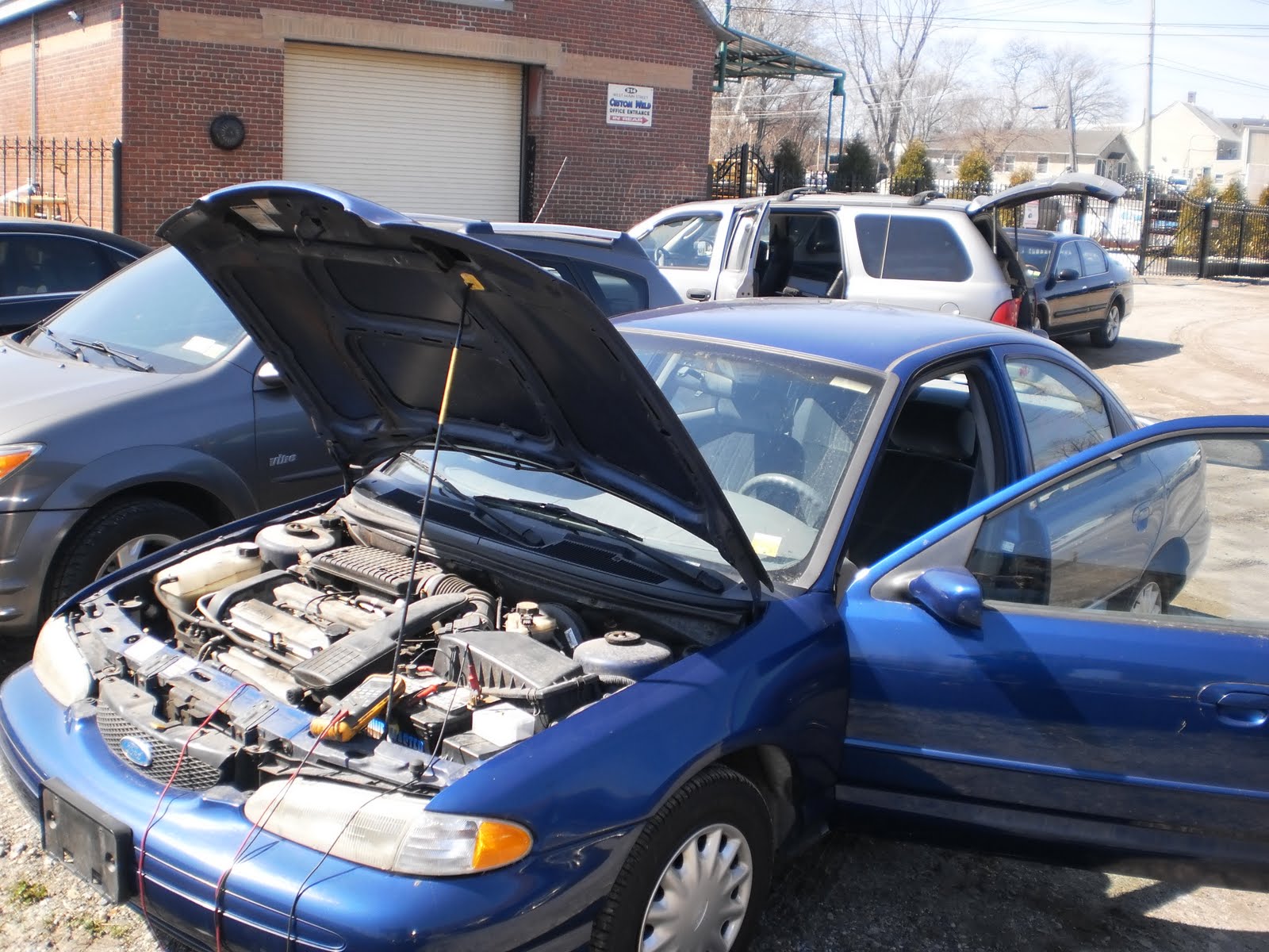
1996 Ford Contour
I am called to Mr. H's shop for a full day of diagnostics. In fact he has so many for me this day I get my own parking lot. I feel special. One of the cars is a 1996 Ford Contour 2.0L with 63,146 miles on the odometer. Car came in with a P0135 code (Bank 1 Sensor 1 Heater Malfunction). Mr. H tried a new upstream oxygen sensor and the code came back immediately. Time to do a little testing. Since this car only has one bank the chances of the wrong oxygen sensor being changed is cutdown. You don't know how many times I have seen this, especially Nissan vehicles. Sure enough the correct oxygen sensor was changed. First things first. Lets make sure we have battery voltage going to our problem child key on engine off. So I backprobe the heater power wire right at the upstream o2 sensor.
Not exactly battery voltage. Now we know why we were setting the heater code. No battery voltage means no heater operation. Time to break out the wiring diagram.
Now we have some directions. Looks like this circuit has a fuse labeled HO2S that feeds both the upstream and downstream heater circuits for the oxygen sensors. Ok, lets check the fuse. this fuse is located in the underhood fusebox. Checking the fuse with a DVOM tells me the fuse is getting battery voltage and the fuse is good. Now what? Lets divide and conquer. We have a connector and a splice joint between the fusebox and the o2 sensors. I always choose connectors over splice joints whenever possible. Reason being connectors are usually easier to find than splice joints. But first look at the fusebox picture.
There is a hole drilled in the side of the fusebox with a snipped butt connector end attached to a wire. When I see this I always get worried. It usually means someone has been trying to "reengineer" the factory wiring instead of repairing it correctly. My catch phrase for this usually goes something like this-"A 100 years of automotive engineering gone in a second." Now, the integrity of the factory wiring is suspect. I follow this rogue wire around the left front strut tower along the firewall to its destination. Of course this wire was not attached to anything. It was defying the laws of gravity in spots.
And there is our destination of the orphan wire. "Expertly" scotch locked to a wire going to the PCM (Powertrain Control Module). Oh boy. Is this our problem? Is this another problem? Was this the remanants of some long ago disabled anti theft device? Well lets get back to testing. As I was saying I always like connectors over splice joints. So I go after C100-located right behind the left front strut tower.
I locate the heater power feed wire at C100.
As you can see I have the same voltage at the o2 sensor at the power side of C100. The power side being the one that is on the power feed side from the fusebox. So now I know my voltage drop is from the underhood fusebox to C100. Remember, divide and conquer. Do I have a rotted wire under the fusebox? It is located right next to the battery. I can't get the rogue wire out of my head. I know it is linked. Hmmm. I start wiggling the HO2S fuse and.....
My meter still stuck in C100 starts to read battery voltage and every voltage in between. Bingo! I pull the fuse out and my first clue is that it pulls out rather easy. I tweak the fuse a bit and reinstall. Same result. I then inspect the fuse cavity.
It doesn't look like much. I removed the fuse next to it for comparison. The terminal is spread open causing contact issues. There is our voltage drop. Now I know where that rogue wire was going at one time. That extra added bulk at the terminal opened it up. Now that there is just a fuse in there (as intended) there is a poor connection. A couple of tries and I was able to close up the terminal sufficiently. A quick run of oxygen sensor amperage on the scanner and a test drive reviewing mode 6 data confirmed the repair.
Not exactly battery voltage. Now we know why we were setting the heater code. No battery voltage means no heater operation. Time to break out the wiring diagram.
Now we have some directions. Looks like this circuit has a fuse labeled HO2S that feeds both the upstream and downstream heater circuits for the oxygen sensors. Ok, lets check the fuse. this fuse is located in the underhood fusebox. Checking the fuse with a DVOM tells me the fuse is getting battery voltage and the fuse is good. Now what? Lets divide and conquer. We have a connector and a splice joint between the fusebox and the o2 sensors. I always choose connectors over splice joints whenever possible. Reason being connectors are usually easier to find than splice joints. But first look at the fusebox picture.
There is a hole drilled in the side of the fusebox with a snipped butt connector end attached to a wire. When I see this I always get worried. It usually means someone has been trying to "reengineer" the factory wiring instead of repairing it correctly. My catch phrase for this usually goes something like this-"A 100 years of automotive engineering gone in a second." Now, the integrity of the factory wiring is suspect. I follow this rogue wire around the left front strut tower along the firewall to its destination. Of course this wire was not attached to anything. It was defying the laws of gravity in spots.
And there is our destination of the orphan wire. "Expertly" scotch locked to a wire going to the PCM (Powertrain Control Module). Oh boy. Is this our problem? Is this another problem? Was this the remanants of some long ago disabled anti theft device? Well lets get back to testing. As I was saying I always like connectors over splice joints. So I go after C100-located right behind the left front strut tower.
I locate the heater power feed wire at C100.
As you can see I have the same voltage at the o2 sensor at the power side of C100. The power side being the one that is on the power feed side from the fusebox. So now I know my voltage drop is from the underhood fusebox to C100. Remember, divide and conquer. Do I have a rotted wire under the fusebox? It is located right next to the battery. I can't get the rogue wire out of my head. I know it is linked. Hmmm. I start wiggling the HO2S fuse and.....
My meter still stuck in C100 starts to read battery voltage and every voltage in between. Bingo! I pull the fuse out and my first clue is that it pulls out rather easy. I tweak the fuse a bit and reinstall. Same result. I then inspect the fuse cavity.
It doesn't look like much. I removed the fuse next to it for comparison. The terminal is spread open causing contact issues. There is our voltage drop. Now I know where that rogue wire was going at one time. That extra added bulk at the terminal opened it up. Now that there is just a fuse in there (as intended) there is a poor connection. A couple of tries and I was able to close up the terminal sufficiently. A quick run of oxygen sensor amperage on the scanner and a test drive reviewing mode 6 data confirmed the repair.
Subscribe to:
Posts (Atom)