This blog will explore the world of automotive diagnostics. We will show a new case study every week.I will also offer my opinions on various issues in the automotive world.
Tuesday, September 9, 2014
Part 2..........
Our next mistaken identity vehicle is a 2005 Infiniti G35 coupe with 61,304 miles on it. Vehicle originally came in for state inspection with the MIL lamp on and many codes. The shop was able to correct many of the issues. They did however have a couple of codes that they could not rectify and the MIL lamp is still blaring away. In New York state if the MIL is on the vehicle will not pass its annual inspection. Ok, lets start by hooking up and seeing the codes and some data. Remember, to click or double click on pictures to make them bigger.
Here, I am using the Nissan Consult 3 scantool. I have a love/hate relationship with this scantool. I love this tool but it is glitchy and has a steep learning curve. It is not very intuitive. When you hook up it will do a VIN check and what is called a system call where it reaches out to see what modules are on the vehicle. The VIN function will be active on 2005 model years and up. It is retrieving the VIN information from the PCM/ECM. I notice something right away here. The VIN on the tool is not the vehicles VIN. I smell some swapped parts. Let's pull codes.
I pull some airbag codes. Yes, the airbag lamp is on and no it is not part of state inspection so the shop owner nor the vehicle owner is concerned about it. The ECM codes are what is putting on the MIL lamp. The P1564 will not illuminate the MIL. By the way ASCD stands for Automatic Speed Control Device in other words cruise control. Given the airbag codes presented it is a good bet this vehicle has a bad clockspring in the steering column.
Now on to the codes that are putting on the MIL. U1001 and U1000. These codes are very common on Nissan/Infiniti vehicles. In fact there is a TSB concerning these codes with certain Freeze Frame data to basically clean all the vehicle grounds. Including the ones on the interior dash support which requires taking half the vehicle apart. I check the Freeze Frame data and it does not match the criteria to clean all the grounds. CAN stands for Controller Area Network. This is a communication data buss that is very common in many vehicles. It is very fast and capable of supporting many modules quite easily. My experience is when I see these codes the module broadcasting these codes is not "seeing" a module that it should. The Consult 3 has a great tool for CAN diagnosis.
This function called CAN Diagnosis Support Monitor is one of the reasons I purchased this tool.
Here I am looking at what the ECM is seeing on the CAN line. OK means it is recognizing and Unknown means it doesn't see it. Looking at the data I can see that TCM (Transmission Control Module) is Unknown. This vehicle is a manual transmission vehicle. This would make sense because this manual transmission doesn't utilize a module. But wait....Something smacks me in the head.
I decide to look at the calibration in the ECM. I run this part number in the Infiniti programming database. By the way NASTF.org will have all the OE websites listed.
This calibration is for G35 coupe with an automatic transmission not a manual. Bingo. That is the reason behind the CAN codes. The ECM is looking for a TCM that is not there. Not seeing it sets the codes and puts on the MIL.
To confirm my theory I drop the ECM down. Which was hanging in by one nut and it has salvage yard writing on it. I advise the shop owner of my findings and tell him he has the option of a used ECM but it has to be the right calibration. A new ECM is pricey. He has to consult with the customer who has already spent a decent amount on this vehicle.
I get a call a couple of days later from the shop owner. A used one is nowhere to be found. A quality remanufactured ECM is not available as well. The customer decides to go new. This is a very pricey ECM. The first thing I do is run this number to see if the calibration is correct for this vehicle.
Looks like we have a winner. The next thing I do is plug it in and check the calibration through the Consult 3. Because, mistakes can happen in packaging.
Looking good. Now, we have to learn the NATS (Nissan Anti Theft System), write the VIN, clear codes, and run a IAVL (Idle Air Volume Learn) routine. Lets get started. But lets check codes first.
No more CAN codes. The P1564 code stays but will not affect MIL operation or prevent this vehicle from passing state inspection. Lets learn some anti theft.
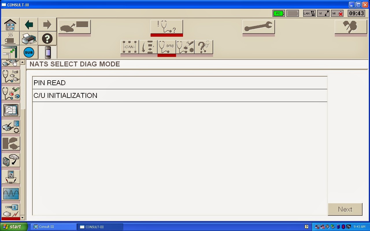
Since this vehicle was receiving a new ECM it is in a auto program mode. It will learn the key without any special procedures. If this was a used or remanufactured unit the following procedure would need to be done in order to learn the NATS. I included the procedure here. First step is to go into the NATS section of the Consult3. This NATS setup requires me to retrieve a 5 digit pin from the BCM then convert it into a 4 digit pin to perform initialization and learn keys. I retrieve the PIN using the PIN READ function.
Before I had this tool I would have to unearth the BCM and try to read the 5 digit PIN on a sticker on the BCM. Not so bad on an Altima or Maxima. Try a Quest. Anyway, now I have the 5 digit code. I use this 5 digit code into a Nissan converter that gives me a 4 digit PIN I can use.
I go into C/U (Control Unit) INITIALIZATION screen and input the 4 digit PIN.
Initialization is complete. But, we are not done yet. We have to actually learn the keys or keys. Consult your service manual for the logistics of this procedure. After we do this the vehicle starts and roars to life. Now we have to learn the VIN.
Using the WORK SUPPORT menu I choose VIN REGISTRATION. This procedure requires entering the VIN twice. I always use capitals.
I complete the procedure which includes a series of key offs and key ons. The next thing I do is close out the application and reboot the Consult 3. I want to see if it pulls the the correct VIN during system call.
Nice!!!!! Now we warm up the vehicle and perform the IAVL routine. Recheck for codes. I tell the shop owner the vehicle is ready to be driven to set emissions monitors. I recall the shop later that day and the shop owner informs me that the vehicle passed inspection no problems.
Tuesday, September 2, 2014
A Case of Mistaken Identity Part 1
Here is one 2001 Saturn L100 vehicle with 111,901 miles on it. The vehicle has been in a collision event and has had a host of "donor" parts installed. The car supposedly ran no problem before being shipped off to the body shop. The trouble at hand now is a start and stall situation. The funny thing is if the battery is disconnected and reconnected the vehicle will start and stay running. Just don't turn it off it will revert back to the start and stall situation. Various people have looked at the vehicle. It was determined that the BCM (Body Control Module) was bad. That is a fair assumption on this vehicle. I do a ton of BCM replacement/programming on Saturn vehicles. A used BCM was installed and still had the same issue. Well, this is where I tell the shop a used Saturn BCM is a definite no no. Saturn BCM's are VIN locked once programmed to a car they cannot be successfully reprogrammed to another vehicle. Yes, you can use them but you will issues such as airbags inoperative due to the VIN mismatch, accessories not working properly, and my favorite mileage change. I do a quick visual on the car and then check for codes.
I pull a U2105 and a U2106 out of the BCM. These are CAN (Controller Area Network) codes concerning module to module communications. Here are the codes and code set criteria.
Something is not sitting well with me at this point. Saturn is like the bastard child of GM. Take what you know about GM and throw it out when dealing with the Saturn platform. It keeps you on your toes for sure. I am looking at these codes and the code set criteria. Something is gnawing at me. I decide to look at some wiring.
I combined both the Saturn L100 2.2 Liter L61 wiring and the 2001 Saturn L300 3.0 Liter L81 wiring together. A couple of observations the L300 L81 utilizes a CAN network and a separate TCM (Transmission Control Module). The L100 L61 platform is pure Class 2 with no separate TCM. I had my first clue. I ask the shop for the replacement used BCM that he used.
No doubt this is a used unit. Junkyard writing galore. It finally hits me. I pop the original BCM out of the car to look at that.
Well they got the same one they had that is for sure. Hmmm it hits me....
They have V6 BCM's!!!!!!!! That is the reason for the CAN codes and the start and stall issue. I inform the shop who tells me how did this happen? I wish I knew. I tell him he needs a new BCM and I will program it for him. The next question is...... wait for it "Why can't I go with a used unit?" "I am losing my shirt on this car" "There is got be another reason"
After informing the shop I will have no part of a used unit he reluctantly agrees.
The new BCM arrives. Notice something different? I install and program the BCM. Relearn the theft deterrent and it start and stays running. Now he can concentrate on the other issues with this vehicle.
Monday, August 25, 2014
New Posts
Sorry gang I haven't posted in a long time. Fortunately, I have been very busy. I have been compiling some new case studies. I have some pet peeves about the industry that I want to write about as well. As always I welcome any input from you the readers. I do have to mention some people that help me remain sane in this crazy business. I will start with my good friend Joey Bag O Donuts he keeps me from going off the deep end and is without question one of the most intelligent human beings on the planet. My buddy that I walk a parallel life with Mike P from Ohio. Johnny from ABC who always comes up with some good stuff and keeps me thinking. Richie from Expert who always talks me up. Dave M. who always gives me an insight into academia and keeps me grounded. Jose J who is a great friend and thinks I should get into Mercedes and BMW-no way Jose. Lenny S who is a tribute to the industry always wanting to do the right job and ask questions. Mike B who is a brother in arms in this crazy automotive diagnostic game. Steven S who is just like me. Also, JT who is the without question the smartest guy in the automotive business. Oh yeah, my wife who puts up with all my bull$%#$ and has to deal with my OCD and the highs and lows of this business.
Sunday, March 2, 2014
Seeing Double Vision-Part 2
Here is a 2008 Dodge Nitro 3.7 Liter with 81,738 miles on it. Shop owner call me with a complaint of MIL on and O2 heater codes that come right back when erased. He is pretty sure it will need a PCM replacement. So sure that he has already ordered the replacement PCM. I told him I will do some quick checks before setting up the replacement PCM. So lets pull some codes.
Again, we are seeing all four oxygen sensor heater codes active. Lets look at some data.
Looking very familiar isn't it? We use the same testing procedures.
Here we actuated Bank 1 Sensor 1 oxygen sensor heater circuit with the WiTECH application at 25%. Again, I want to look at the command and amperage. We are flowing about 2 amps of current when activated. Lets look at static reading as well.
Same testing procedure as on the Jeep. We are checking resistance.
Here is the resistance of Bank 1 Sensor 1 oxygen sensor heater circuit-the whole circuit.
Here is the replacement PCM. Again, this is not a plug and play unit. Same procedures as Jeep.
Here I used the WiTECH application to program the replacement PCM.
The data after the PCM replacement. Now, are we to assume that whenever we get all O2 heater circuit codes at the same time that it is always the fault of the PCM? You better not. I try to treat each instance as brand new. If you don't you could make a wrong turn on your diagnostic path. Do the testing and confirm.
Sunday, February 23, 2014
Seeing double vision-Part 1

This winter has been brutal here in the Northeast. It makes everything harder. So here is a little something to warm you up. Well it is more like warming oxygen sensors up. Lets talk oxygen sensor heaters. Here is a very popular vehicle. This 2008 Jeep Wrangler with 50,731 miles and a 3.8 liter in it has a MIL lamp on. The shop tells me he is getting O2 sensor heater codes that come right back immediately after clearing. He has tried some new O2 sensors and still has issues. Lets take a look at the codes.
I always do a quick visual before hooking up my scantool. Lets pull the codes.
I am using the factory scan tool WiTECH. I see O2 heater codes for all four O2 sensors and they are active. Active meaning the fault is there right now. As opposed to stored where the fault happened some time ago but is not occurring right now. Now when I see all four O2 codes I immediately think of two issues. One being wiring and the other being the PCM itself. If this vehicle was flagging one O2 heater code it is feasible that it may be the sensor itself. A couple of important notes. These vehicles do not seem to tolerate aftermarket oxygen sensors. It is always better to go with an OE sensor. The other is that the O2 heater is a learned value. A bad oxygen sensor may cause a heater code and after replacement it may still flag a heater code. A PCM reset is in order after sensor replacement. The easiest/most definitive way is to disconnect a battery cable for 10 minutes or so. Back to the situation at hand. Lets look at the circuit.
What is a little unusual on Chrysler NGC O2 heater circuits is that the heater element is grounded all the time and the PCM (NGC Controller) pulses 12 volts to light up the heater. Typically on a cold motor the PCM will duty cycle the heater more and then lessen duty cycle as the vehicle warms up. It is all in an effort to get that vehicle in to a closed loop/feedback situation as quickly as possible. In the automotive world it all revolves around CAFE (Corporate Average Fuel Economy). I want to test
this circuit.
I want to check the circuit dynamically and statically. I first locate pin locations at the PCM. In this case Bank 2 Sensor 1 heater circuit is at terminal #17 at the PCM connector with the orange insert. Lets hook up.
I backprobe the wire here and also I am going to put a low amp probe around this wire as well. I want to see the PCM actuate the heater and what kind of amperage we have on the heater circuit.
But, first lets look at some data. What does the PCM think. As you can see here the PCM is not actuating the heaters. They are at 0%. Look at the O2 heater temp pids. Strange, right? This is a calculated value that the PCM formulates through an algorithm programmed into the PCM. Well if the PCM will not work the circuit, how can we?
Using WiTECH or a full function scan tool we can actuate the heater circuits in increments up to 25% on this application. Lets get the scope on there.
Here is Bank 2 Sensor 1 heater circuit. What I am looking for is a one to one relationship between actuation and amperage. Clean transitions and proper amperage. Looks good so far. This is a dynamic test. This test is done key on engine off. Looking at the amperage and using Ohms Law we can figure out our heater resistance as well. On time is our 25% commanded. Lets look at Bank 1 Sensor 1 heater circuit.
More of the same here. At this point my static testing will be academic. But lets do it anyway.
I am testing static O2 heater resistance. One lead is in the PCM connector and the other is to ground.
Remember what I said about figuring out heater resistance with the voltage and amperage scope shot. Well here you go we were pulling just under an amp. 12 volts with a 14 ohm load nets you about .85amps. The downstream O2 heater circuits are on a different PCM connector.
Upstream and downstream resistance specs can be different. As such is the case here. I check all four heater resistances at the PCM connectors. It is important to do testing as close to the PCM as possible. It is one stop shopping. It checks wiring and the component in one step. At this point it is looking like a bad PCM. I inform the shop owner.
Here is the old PCM.
New PCM installed. This Chrysler PCM/NGC comes blank. It needs the correct calibration programmed into it, the theft system reinitialized, the VIN and mileage programmed, the ETC (Electronic Throttle Control) relearn, and a Quick Learn for the transmission.
I programmed the PCM using Chryslers predecessor to WiTECH which is Starmobile/Desktop Client. After programming I went back to WiTECH to recheck pids.
Ok now look at those pids. That is what we want to see. Lets recheck codes.
I am feeling warm on this frigid day. See you soon for Part 2........
Sunday, January 19, 2014
2002 Ford Explorer
Here is a 2002 Ford Explorer with 134,462 miles on it. Yes, that is my fat finger in the photo. The shop owner called me in for an intermittent or no communication with the PCM. This was preventing the vehicle from passing state inspection. There were no real driveability issues with this vehicle. The shop and the owner just wanted to get it to pass state inspection. The shop owner has tried two different scantools and the state inspection machine. All having communication issues. I plugged in the Ford IDS factory scantool and had no issues communicating. Plugging in an aftermarket tool I have I was greeted with no communication just like the shop owner said. Ok, lets get going here.
SCP data buss is a two wire data buss. The two wires are for redundancy. One wire is pulled high and the other is pulled low. They should be mirror images of each other although moving in opposite directions. From the diagram you can see that on this early build (check production date) there are three modules on the data buss. The PCM, EATC (which this vehicle had), and the Instrument Cluster. Lets get a scope on those data lines.
I see issues already. I see Terminal #10 full of activity and Terminal #2 is not a mirror image. I also am not pleased with the amplitude of the signals. SCP is typically a 5 volt amplitude signal. Lets zoom in.
I zoomed in when we did have activity on both wires. A sloppy signal but pretty much a mirror image. Now what. Do I have a module causing problems on one leg of the SCP? What about the low amplitude? Do I really want to start popping out an instrument cluster. I quickly look for any type of aftermarket device such as an alarm or remote start tied into the SCP circuit. There was and I removed it and still had same issue. The DLC is mounted vertically on this vehicle. I unbolted it so I could get a good look at it.
I see something that catches my eye immediately.
Terminal #2 is spread. In fact all the terminals on the top row are spread open. Years of scantools being put on the DLC and then yanked off at an angle spread the terminals apart. This DLC is mounted vertically and that is what contributed to this. I quickly check my theory by using a spare DLC male pin I use to check terminal tension and that confirms my theory. I gently squeeze terminal #2 down a bit and recheck my scope pattern.
Much better. More importantly hooking up various scantools yields communication every time. I am still perplexed by the low amplitude and the ragged signal. I have scoped this signal before and it never looked like this. I advised the shop owner that the DLC should be replaced with a quality replacement pigtail assembly. I give him a part number. Now why weren't the aftermarket scantools communicating and my IDS did.
The reason is that the aftermarket tools will initiate communication through pin #2. Where the IDS will be a little more forgiving and will communicate on pin #10 as well. Remember, the redundancy of the SCP buss. Engineers built that in in case one leg goes open or shorted. As I drive away from the shop the low amplitude/ragged pattern of the data buss is gnawing at me. Is there something wrong with my scope? I am reviewing my testing in my head on the way to the next job. Those that know me, know that this is eating away at me right now. I own a similar truck with a SCP buss. When I get home I will check it. That night I get home and check the SCP data buss on my own truck and get the same low amplitude/ragged pattern. At this point I am thinking it is a tooling issue. I then realize that I had my filters set to "on". Using filters is great for filtering out some noise but can through you off on some signals. Taking the filters off nets me this proper pattern.
That is more like it. The lesson here is know your tooling and how it operates during some applications. The other is don't overlook the obvious such as spread terminals.
Subscribe to:
Posts (Atom)