
I get a call from a shop owner. He explains he had this 2002 Mitsubishi Montero Sport 3.0 liter towed in for a no start. They found a broken timing belt. He explained to the customer that the timing belt broke and there may be valve damage from the broken timing belt. Some engines are interference and others are non interference. Another factor to consider here is the vehicle is being towed in as a no start. The shop has no way of knowing how the vehicle ran prior to the timing belt breaking. The customer gives the okay for the timing belt replacement. The timing belt is replaced and the vehicle starts but runs poor. It has a very rough idle and a misfire. Now, the shop owner is wondering is the timing belt installed right? Are there further issues? He calls me and wants me to check it out. I arrive at the shop and the vehicle starts and definitely runs poor with a misfire. Now, I need to give you some setup on my next step.

Here is my high amp probe. It has a 600 amp capacity. It is different from my low amp probe in its capacity and scaling. Basically, with this probe 1mv equal 1 amp. It's large jaw capacity is a necessity for the next test I want to perform. I want to check compression on this vehicle. I don't want to spend all day taking spark plugs out and on this vehicle removing the upper intake to gain access to half the spark plugs. We are going to do a relative compression test. It is one of my favorite tests. Easy to do and packed with information. This test will measure the amount of electrical current needed to turn the motor over as it relative to each cylinder. What we are looking for is uniformity between cylinders. We are also looking for a proper cranking amperage as well.

To perform this test I disable fuel accordingly. You want no fuel flowing into the cylinders and washing them down giving you inaccurate testing. Then I setup my scope with amp probe around a battery cable with the arrow on the clamp in direction of current flow. Then we are going to crank the engine over, record, and analyze the results. A couple of key points here. You must have a good battery and starting system. No battery chargers. A jump box is acceptable. A donor battery is sometimes needed if the vehicles battery wont support 20-30 seconds of cranking. Lets give it a crank.

Here we have some cranking time on the screen. What we are looking for is uniformity. We are also looking for about 150 cranking amps and about 30-40 amp differential between high and low points. We have about 4000ms of time which is 4 seconds. I see something that stands out.

I zoomed in a bit here and highlighted what I saw. Every sixth pulse is low. The pulses are representative of our six cylinders. We have about 150 amps and approximately 30-40 amps from high to low. Now, we know we have a cylinder that has substantially lower compression due to the low amperage load to "turn" that cylinder. The next cylinder after a low cylinder will usually be a higher amperage load as it "catches up" so to speak. Ok, so we know we have a low cylinder. But, which one?

Our next tool is an ignition synch probe. This will go around an ignition wire and will display a pattern when spark is flowing through the ignition wire. This pattern will not be detailed like a true blue ignition probe but all we are looking for is a reference here.

I place the probe around number one ignition wire. Crank the engine over again. The shop left the timing belt covers off here.

Now, we have some reference to work with. The large green spikes are cylinder number one firing. Most vehicles will crank somewhere near TDC so the spark spike should split the relative compression spike right in the middle. That looks good here. Now we can find out our low cylinders identity. Let's mark it up.


I marked it up with the firing order. Now we can definitely say that cylinder number 3 is not happy. Do we have a hole in the piston, a valve not seating, a broken valvetrain component? Well we really can't say from this. But, we saved about 2 hours of labor. In 15 minutes we are here and the most labor we did was to disable the fuel system. I do a couple of more tests before talking to the shop owner.

I scope crankshaft and camshaft sensors to see if the timing belt is correctly installed. Typically, if the timing belt was incorrectly installed it wouldn't affect one cylinder it would be multiple cylinders. But, it only takes a minute.

I compare our pattern to the service information and it looks dead on. Please note that service information is different than my scope pattern as far as placement of signals. The service information has the crank sensor pattern on top where as I have it on the bottom. I always put my crankshaft sensor pattern on the bottom and I always use channel 1. It is the OCD coming through.
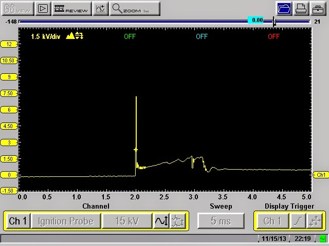
I look at the ignition pattern on a known good cylinder. In this case it is cylinder number one. We have about a 7.5 KV spike and noticeable cylinder turbulence in the firing line. This cylinder is working. Lets look at cylinder number 3.

Here is our bad cylinder low 3KV spike, a long firing line, and no turbulence at all. This cylinder is not contributing. It is like its firing the plug in the atmosphere instead of a combustion chamber. I inform the shop owner of the correct timing belt installation and the low number 3 cylinder. I advise him that from here we can do a leakdown test or I can use a pressure transducer in the cylinder coupled with a vacuum waveform to pinpoint the issue. He tells me he will take it from here. Cylinder three is accessible without taking the upper intake off. The whole idea here is to work smarter not harder. The tooling used here is within the reach of most techs.
.JPG)
.JPG)
.JPG)


.JPG)
.JPG)
.JPG)
.JPG)

.JPG)